Hi
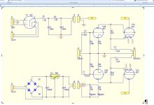
I bought from ebay a SRPP kit pream based on 6N3P.Please how can I reduce the gain because it is too high for my John Linsley Hood Amplifier.V+ is 200 V dc
thanks
I bought from ebay a SRPP kit pream based on 6N3P.Please how can I reduce the gain because it is too high for my John Linsley Hood Amplifier.V+ is 200 V dc
thanks
Attachments
Last edited:
Try increasing all of the 470R to around 1k each.
If you need to reduce the gain a lot, an overall feedback loop
can be added to this inverting circuit.
If you need to reduce the gain a lot, an overall feedback loop
can be added to this inverting circuit.
Last edited:
Install a volume pot.Hi
I bought from ebay a SRPP kit pream based on 6N3P.Please how can I reduce the gain because it is too high for my John Linsley Hood Amplifier.V+ is 200 V dc
thanks
The implication is that he has a volume control, but it has to be turned way down
for a normal volume level.
for a normal volume level.
That's why a volume/level control in the srpp make sense.The implication is that he has a volume control, but it has to be turned way down
for a normal volume level.
He can certainly add an L-pad attenuator at each input.
Having two volume controls in series doesn't make much sense, though.
Having two volume controls in series doesn't make much sense, though.
Last edited:
PCB kits are difficult to modify.
Point to Point wiring would allow you to parallel 2 triodes, individual self bias each triode, and take the output off the parallel plates (rp/2).
The self bias could be used with no bypass capacitors, and the self bias resistors and plate load resistor values could be adjusted to get the gain that is desired. But watch the B+ dissipation, it needs to source 2X the current, when using parallel triodes, versus SRPP.
Or, use a triode with lower u, and adjust the 470 Ohm resistors to get the quiescent current to make the lower u triodes to operate in a linear region (but watch the B+ dissipation, if the tube requires higher plate current).
Again, with a PCB, you can not pick just any dual triode, you are stuck with the 6N3 pinout.
No 12AU7, no 12BH7, etc.
Is there a lower u Russian dual triode with the 6N3 pinout?
Last edited:
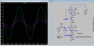
Try this mod. Added 2 resistors as sch. attached, they reduce gain by introducing degeneration or local feedback. Pick the resistors up to 10k. The mod does not change the operating points as bias and current are same, just reduce gain. You can't reduce gain by simply changing SRPP cathode resistors.
Attachments
True but OP could use an adapter like this: 2Pc Gold plated ECC88 6922 6DJ8 instead 6N3 5670 tube converter adapter | eBayAgain, with a PCB, you can not pick just any dual triode, you are stuck with the 6N3 pinout.
No 12AU7, no 12BH7, etc.
or any other 6N3-to-xx tube available at various vendors.
Yes,it's called 6N3P (Cyrillic 6Н3П),with the usual -E,-EB or -ДR (- E,-EV,-DR) terminations.Data here: http://istok2.com/scan/575_1.gifIs there a lower u Russian dual triode with the 6N3 pinout?
The gain of 6N3P is 24.6 dB in SRPP circuit. It is not possible to reduce it by changing the cathode resistors. The only possibility is to use a lower μ tube. The μ of 6N3P is 36.
6DJ8/ECC88 would give about the same gain.
6DJ8/ECC88 would give about the same gain.
Last edited:
Then we are back to a voltage divider, using a pot one gets a adjustable divider.The gain of 6N3P is 24.6 dB in SRPP circuit. It is not possible to reduce it by changing the cathode resistors. The only possibility is to use a lower μ tube. The μ of 6N3P is 36.
6DJ8/ECC88 would give about the same gain.
Sorin Cristea,
Good points!
Lots of solutions for the OP.
Just remember that adapters require a taller case to contain the tubes,
or he can just cut out holes in the top cover and have part of the tube sticking out above the cover.
Good points!
Lots of solutions for the OP.
Just remember that adapters require a taller case to contain the tubes,
or he can just cut out holes in the top cover and have part of the tube sticking out above the cover.
rongon,
If the preamp is on a PCB, and he does not want to cut any traces, then . . .
Shunt feedback would have to go from Plate # 1 to Grid #1.
It would need to have a resistor and coupling cap in series (to block DC to Grid # 1).
It would lower the input impedance of the preamp (require a lower signal source impedance).
(Plate #2 is at B+, so there is no signal there, and so has nothing to feedback to Grid #1).
...how can I reduce the gain because it is too high for my Amplifier...
You could place a voltage divider at the output side. Distortion is key here as there is an optimal value to the circuits' load. Some modelling is telling a lot.
Re: shunt feedback
Well, that's a bummer. I see that there isn't even a grid stopper that could be used as the series resistor.
Why not just put a pot on the input then? A plain old volume control?
If you put the voltage divider (or pot) on the output, the SRPP will be operating with full input signal level all the time. Since THD is proportional to level (the higher the level the higher the THD), it will add THD to the system. Or would that be a desirable attribute?
On the other hand, if you can find the distortion null, you could design the voltage divider to present that impedance to the output of the SRPP. That would be pretty slick. But how stable is that null? Would it be the same for any 6N3P, 5670 or 2C51?
Last edited:
If you put the voltage divider (or pot) on the output, the SRPP will be operating with full input signal level all the time. Since THD is proportional to level (the higher the level the higher the THD), it will add THD to the system. Or would that be a desirable attribute?
On the other hand, if you can find the distortion null, you could design the voltage divider to present that impedance to the output of the SRPP. That would be pretty slick. But how stable is that null? Would it be the same for any 6N3P, 5670 or 2C51?
Yep, I did this 10 yrs ago -with an 12AH7 I recall- but the thread seems erased now. All the calculus was in it and some explication from Merlin too.
- Home
- Amplifiers
- Tubes / Valves
- Srpp preamp