Hi docali,
No, the circuit reported from you is
an SRPP variant that, as I have read, works very well
if correctly implemented.
I have not proposed a working circuit,
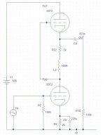
but a theoretical circuit (on the right) equivalent to the SRPP.
Its performances (freq. resp, harmonic distortion, etc.)
are identical to those of the standard SRPP (on the left).
It is only a different view of the same circuit.
Maybe someone, by looking at this non operative
circuit will find some good ideas.
or will reach a better understanding
of the SRPP circuit.
I don't know.
bye
Federico
No, the circuit reported from you is
an SRPP variant that, as I have read, works very well
if correctly implemented.
I have not proposed a working circuit,
but a theoretical circuit (on the right) equivalent to the SRPP.
Its performances (freq. resp, harmonic distortion, etc.)
are identical to those of the standard SRPP (on the left).
It is only a different view of the same circuit.
Maybe someone, by looking at this non operative
circuit will find some good ideas.
or will reach a better understanding
of the SRPP circuit.
I don't know.
bye
Federico
SRPP with inductors are certainly interesting creatures. with 25uH and a 12AT7, I got one to be +-6dB from 5Hz to just under 10MHz 😎
I do not see the two circuits being equal...
The circuit on the right is not in series and does not get the benifiets of the circuit on the left...Cirsuit on Right is a Common cathode direct coupled to a cathode follower...
The inductor in the cathode does not seem to have any advantage...possibly a disadvantage...
SInce the output impedance of the follower is dominated by the impedance looking into the cathode....and that is in parallel with the L which could introduce capacitance and loss of highs......
Chris
The inductor in the cathode does not seem to have any advantage...possibly a disadvantage... SInce the output impedance of the follower is dominated by the impedance looking into the cathode....and that is in parallel with the L which could introduce capacitance and loss of highs......
Only at very high frequencies or with a poorly chosen choke, yes, but putting a choke with a CF is not inherently a bad (or a new idea) idea. It is generally desirable to make the cathode load of a CF stage have a very high AC impedance, and a choke has advantages in this role. If a choke's capacitance is a problem interacting with the low resistance of the cathode in a CF, then that same choke would behave even worse (lower roll-off frequency) working against the higher plate resistance in a common cathode stage, where we see it more commonly. In either case, series resistors are often used to set DC operating points, only serving to further isolate shunt capacitance, and to prevent possible oscillation in CFs.
cerrem said:I do not see the two circuits being equal...
Ahh, but they are!
The circuit on the right is not in series
No, but for theoretical work you assume I1 = I2 anyway.
The inductor in the cathode does not seem to have any advantage...possibly a disadvantage...
Oh, it has advantage, namely of removing any loading resistance. This allows you to see the only impedance at the 2nd triode's grid (and cathode) is the preceeding tube's plate resistance.
Of course it isn't a perfect cathode follower, rather only bootstrapped, so the 2nd cathode has a loading effect too, depending on output load impedance. That is why this circuit is imperfect; an infinite AC impedance in the 2nd cathode would decouple output nicely from the 1st triode, allowing constant current operation of the bottom triode, while providing classy CF output.
SInce the output impedance of the follower is dominated by the impedance looking into the cathode....and that is in parallel with the L which could introduce capacitance and loss of highs...[/B]
Huh? Whatchoo talkin' bout there? From what I see, this circuit goes well into the UHF range.
Parasitic circuit elements are for engineers, not theorists 😉
Tim
Konnichiwa,
Except, it is not equivalent, NOR does it behave like one. SRPP is a direct push-pull circuit....
Sayonara
fscarpa58 said:enclosed an SRPP equivalent circuit.
Except, it is not equivalent, NOR does it behave like one. SRPP is a direct push-pull circuit....
Sayonara
hi
I leave that everyone draws theirs own conclusions.
Those which succed in seing the math. equivalence
will also succeed, maybe, in doing some valid
development.
Federico
I leave that everyone draws theirs own conclusions.
Those which succed in seing the math. equivalence
will also succeed, maybe, in doing some valid
development.
Federico
I for one appreciate it, though it isn't a revelation to me. I suppose the others in this thread would also object to calling the supply line grounded in AC analysis.
Tim
Tim
The circuit is identical to a SRPP for AC given that the inductors are infinite, (when they can be ignored) but what is the benefit of the model?
Of course it is not identical to a SRPP for DC.
Regards Hans
Of course it is not identical to a SRPP for DC.
Regards Hans
Hi
why not? same DC currents, same DC voltage.
but this is not the point.
The point is: Does such a circuit suggest you something? No?
Nor to me but,...
I think that it is a good thing to have our brain working and
searching.
For instance look at the following buffer circuit (left pic)
It is a variant of the White cathode follower.
Now looks on the right. This circuit is equivalent but
it can be simplified by removing upper res. and cap.
(there is a little change in the working point but it is not important).
The cost is in the floating supply.
bye
Federico
Of course it is not identical to a SRPP for DC.
why not? same DC currents, same DC voltage.
but this is not the point.
The point is: Does such a circuit suggest you something? No?
Nor to me but,...
I think that it is a good thing to have our brain working and
searching.
For instance look at the following buffer circuit (left pic)
It is a variant of the White cathode follower.
Now looks on the right. This circuit is equivalent but
it can be simplified by removing upper res. and cap.
(there is a little change in the working point but it is not important).
The cost is in the floating supply.
bye
Federico
Attachments
This thread is very interesting, I'm following it closely, I can see how the two circuits in the first post are similar, and how they would both behave in a similar manner, It would be interesting if someone were to build the two in somethign like circuitmaker and show us some figures for both circuits. I'd do it myself but i dont really have the experience.
Owen
Owen
hi
If one simulates the circuits with very great inductance values of, for example, 10k H, then the behaviors are identical with respect
to both freq. response and distortion. I did it with MicroCap.
Federico
If one simulates the circuits with very great inductance values of, for example, 10k H, then the behaviors are identical with respect
to both freq. response and distortion. I did it with MicroCap.
Federico
why not? same DC currents, same DC voltage.
Yes, but only for static conditions if the anode of the first tube is always exactly half of the supply voltage. For instance if one of the resistors are changed the circuit is not valid anymore as there will be current drawn from the V/2 sources.
Maybe I am nitpicking but I like models to be accurate also for DC sweep.
Regards Hans
makes sense, what would happen if the inductance values were to be lowered? Or would that just throw the whole circuit into a great ball of distortion and flames and stuff? .o0( actually that sounds pretty cool)
Owen
Owen
It works for AC analysis. For DC stability you can assume I1 = I2 (and the respective voltages) and then see how they interact.
Tim
Tim
if one of the resistors are changed
I agree, but that will be an other circuit.
The circuit are identical only in the sense that, in the above
conditions, they show identical freq. resp. and distortion
spectrum.
They are different with respect to other parameters, eg. PSSR.
(obvious, you'll say).
by
Federico
I understand the purpose of Federico in proposing this conceptual topological equivalence.
The only idea the circuit suggest to me is: what about the two inductance were coupled (part of a transformer)?
The only idea the circuit suggest to me is: what about the two inductance were coupled (part of a transformer)?
what about the two inductance were coupled
interesting point!
this is the right mind-set
ciao
- Status
- Not open for further replies.
- Home
- Amplifiers
- Tubes / Valves
- SRPP: adifferent perspective