hi
as you see, I have some time today, so I propose to you a little game. I'll reveal you a new fantastic ( I am joking ) circuit but I'll do it step by step.
the first step is this: look at the following pic,
you can see an SRPP implemented as a buffer (unit gain) on the left and a slight different circuit on the right.
pay attention to the position of the capacitor and of the ground.
where it will be the bigger difference between the cirs.?
which performance is more affected
I' see you tomorrow.
Federico
Attachments
No difference for F > F3 of the RC output combo. You've got to be careful when moving caps though, don't want to fudge the bias with respect to the input. 🙂 (No problem given a coupling cap.)
Tim
Tim
ok , ok
you are correct but...
I think F3 refers to RC comb. of first cir.
and for F<F3?
what about the -3db freq. of the second cir?
what about the Zout of the 2nd cir at low freq.?
Federico
you are correct but...
I think F3 refers to RC comb. of first cir.
and for F<F3?
what about the -3db freq. of the second cir?
what about the Zout of the 2nd cir at low freq.?
Federico
hi
you guys do not like this game, however...
the following is the comparison of performance between
the two circuits.
freq. response and output impedance.
the difference is sharp.
circuits (b) operates like if its opt. capacitor has a much greater
value.
Federico
you guys do not like this game, however...
the following is the comparison of performance between
the two circuits.
freq. response and output impedance.
the difference is sharp.
circuits (b) operates like if its opt. capacitor has a much greater
value.
Federico
Attachments

A is dominated by the output coupling cap, while B is dominated by the input coupling cap (frequency is in the 1/minutes range because the cathode follower has a bootstrapped input impedance). B is still limited by the output cap, but with respect to the same signal ground as the input, it isn't seen in the data.
At least that's what I *think*. The output coupling cap should still effect Zo...
Tim
At least that's what I *think*. The output coupling cap should still effect Zo...
Tim
I tim
I set the input capacitance to be very large ( 10000 u) so it is like a wire and it does not influence the performance.
Circuit (B) is by far better.
It allows the use of a smaller (so often of higher quality) cap for
the same performance.
Way I never seen it? People fear floating PSU?
yes, it can happen that one has to implement multiple PSU
( one per channel, as an example)
but, in a non commercial design , it is not a big problem.
Federico
hi tim
I am not sure to understand, however..
I am making calculation to find out the equivalence.
That is, which value of capacitance in circuit (A) makes it
equal to circuit (B)
bye
Federico
Oh, then it must be Zo vs. Co as opposed to Rl vs. Co.
I am not sure to understand, however..
I am making calculation to find out the equivalence.
That is, which value of capacitance in circuit (A) makes it
equal to circuit (B)
bye
Federico
Ah, I see clearly now.
The differences is appearances only: A's input is grounded to the battery, while B is grounded to the load's common terminal. Thus in B, the amp's input-signal return is after the capacitor, and the battery floats on any voltage induced in C.
This form shows it better I think.
Tim
The differences is appearances only: A's input is grounded to the battery, while B is grounded to the load's common terminal. Thus in B, the amp's input-signal return is after the capacitor, and the battery floats on any voltage induced in C.
This form shows it better I think.
Tim
Attachments
Why not use Gomez like alternative to SRPP ?
http://digilander.libero.it/paeng/design_frame.htm
[]´s
João
http://digilander.libero.it/paeng/design_frame.htm
[]´s
João
fscarpa58 said:I think Gomes is a very good performer.
The question is.
Is there something better?
Federico
Yeah, instead of shoehorning in four triodes in a whacky arrangement, use one one or two as appropriate for the circuit! 😀 Less is more...
Tim
Tubecad have a excellent compare between SRPP, GOMEZ, AIKIDO, XPP
See:
http://www.tubecad.com/2004/blog0015.htm
[]´s
João
See:
http://www.tubecad.com/2004/blog0015.htm
[]´s
João
cerrem said:
SInce the output impedance of the follower is dominated by the impedance looking into the cathode....and that is in parallel with the L which could introduce capacitance and loss of highs......
Chris
exactly
thanks
lineup
cathode follower DC coupled output ...
Thanks lineup,
for bringing up this interesting thread.
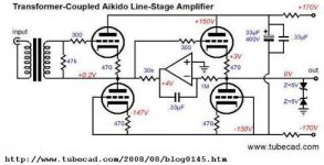
J.B. Took this idea in his august blog. 😉
Please note that the bottom triode is not a constant current source.
A ccs makes an improvement here. SY did it.
http://syclotron.com/?page_id=25 😎
Now imagine the opamp and the ccs replaced by triodes ...
"Tarzan in New York"
V10_cathode follower
V9_ccs (note that grid is positiv with respect to cathode)
V5;6;7;8_opamp
Kind regards,
Darius
Originally #36 posted by lineup
exactly
thanks
lineup
Thanks lineup,
for bringing up this interesting thread.
Originally #25 posted by fscarpa58
hi
you guys do not like this game, however...
the following is the comparison of performance between
the two circuits.
freq. response and output impedance.
the difference is sharp.
circuits (b) operates like if its opt. capacitor has a much greater
value.
Federico
J.B. Took this idea in his august blog. 😉
Please note that the bottom triode is not a constant current source.
A ccs makes an improvement here. SY did it.
http://syclotron.com/?page_id=25 😎
Now imagine the opamp and the ccs replaced by triodes ...
"Tarzan in New York"
V10_cathode follower
V9_ccs (note that grid is positiv with respect to cathode)
V5;6;7;8_opamp
Kind regards,
Darius
Attachments
Re: cathode follower DC coupled output ...
SRPP Shunt Regulated Push Pull is interesting.
As some JFET transistors (N-Channel) are quite similar to Triodes (N-Channel),
SRPP is something we can try for JFET, too
This is why I have searched for SRPP stuff, here in forum & from internet.
I have found some JFET SRPP Ciruits here, in Pass Labs forum
http://www.diyaudio.com/forums/showthread.php?postid=1586486#post1586486
The master him self 😎 Nelson Pass 😎 ... posted last post
I do not know much about SRPP. I am still learning.
Only thing I know is .. it can improve some amplifier stages
.. if handled in a correct way
Regards 🙂 Lineup
oldeurope said:
Thanks lineup,
for bringing up this interesting thread.
J.B. Took this idea in his august blog. 😉
Please note that the bottom triode is not a constant current source.
A ccs makes an improvement here. SY did it.
http://syclotron.com/?page_id=25 😎
---------------
Kind regards,
Darius
SRPP Shunt Regulated Push Pull is interesting.
As some JFET transistors (N-Channel) are quite similar to Triodes (N-Channel),
SRPP is something we can try for JFET, too
This is why I have searched for SRPP stuff, here in forum & from internet.
I have found some JFET SRPP Ciruits here, in Pass Labs forum
http://www.diyaudio.com/forums/showthread.php?postid=1586486#post1586486
The master him self 😎 Nelson Pass 😎 ... posted last post
I do not know much about SRPP. I am still learning.
Only thing I know is .. it can improve some amplifier stages
.. if handled in a correct way
Regards 🙂 Lineup
Re: Re: cathode follower DC coupled output ...
Hi Lineup,
#25 is a cathode follower. 😉
schematic #25
Should I start a new thread for DC coupled cathode follower outputs ? 😕
Darius
Hi Lineup,
#25 is a cathode follower. 😉
schematic #25
Should I start a new thread for DC coupled cathode follower outputs ? 😕
Darius
How come the B) has so much better low freq rolloff?
Is it because B) has got Ground separate from power supply?
Maybe some kind of floating supply.
Or maybe simply because the CAPACITOR in B) is much bigger than 2 uF
No, do not start any new topic, at leat not for my sake.
I prefer we have all these nice SRPP schematics in one place.
But do as you wish.
Regards
- Status
- Not open for further replies.
- Home
- Amplifiers
- Tubes / Valves
- SRPP: adifferent perspective