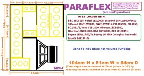
I suggest concentrating on getting the external dimensions and the panel width to match the actual build and the areas at S1 (the start of the line) and S4 (the end of the line) to match the actual build. Then use the "Optimize" feature - the intent is to get the number highlighted in red as close to zero as possible. Just keep clicking on the "Optimize" button until that happens. The result should be a layout pretty similar to what you built. Don't be too concerned with minor differences.
Ok awesome, thanks! And then I just update S1 to S4, Vtc and Atc in hornresp? Do I leave the three Par values at as they are (from Anders' original model)?match the actual build and the areas at S1 (the start of the line) and S4 (the end of the line) to match the actual build
The Hornresp sim figures generated in the spreadsheet are likely going to be more accurate.
Ok, another stupid question sorry - are the three par figures to transpose to hornresp L12; L23 and L34 in the spreadsheet? I must have input some incorrect panel dims as my L34 seems too high and throws the modelled response out.The Hornresp sim figures generated in the spreadsheet are likely going to be more accurate.
Yes. If you use the "Export Sim" option in the workbook, it will automatically generate a file containing the sim's parameters, which you can then import into Hornresp using its "File..Import..Hornresp Record" feature.
Fixed the macro in 64 bit and happily imported! 🙂 thanks ! The optimised model from the spreadsheet is not too far off measured, but still measuring a 180ish dip when Hornresp predicts a peak. arrgh! 🤦♂️😆 Should I post a graph here or over on the Tham15 thread? I have a sense that the L34 value influences that particular peak/dip in the hornresp graph - is that the length from the driver to the horn mouth? Maybe it's back for more study of hornresp fundamentals for me.import into Hornresp
Last edited:
Should probably use the THAM thread to discuss the THAM design. I suspect that the dip where a peak was predicted has something to do with the folding near the mouth of the THAM TH. The effect of that folding won't be predicted by Hornresp. I went back and looked at the response curves for a THAM-style TH I built years ago and yes it looks like I measured a dip around that frequency too, though it wasn't deep enough to remove the peak entirely. See https://www.diysubwoofers.org/projects/other/POC2/
And it still looks good in a SUV! It's amazing how you didn't lose output with the dog food duct.
Hi everyone,
those workbooks are amazing, thanks for sharing them with the community!
I am trying to use the SFTH and SFTH2 workbook, but I always get an error in Hornresp when I try to import the record (invalid record).
Am I missing something?
those workbooks are amazing, thanks for sharing them with the community!
I am trying to use the SFTH and SFTH2 workbook, but I always get an error in Hornresp when I try to import the record (invalid record).
Am I missing something?
It's not just those two workbooks that are affected. I tried a few others and I'm getting the same results. Looks like something's changed recently in Hornresp that's affected the import of the files created by the BOXPLAN scripts. I'll put a note about it in the Hornresp thread. In the interim, they are basic text files, so you can open them in Notepad and input the values into Hornresp manually.
Looks like something's changed recently in Hornresp that's affected the import of the files created by the BOXPLAN scripts.
The bug has now been fixed.
https://www.diyaudio.com/community/threads/hornresp.119854/page-709#post-7577260
Based on your observation that the extra chamber would be useful to mitigate the 5th harmonic of the transmission line design (the 3rd harmonic mitigated by the 1/3 offset), is it possible to add this design to the sheets?
Regards,
Giri
Brian,
when i import a driver from HR on the cubo spreasdheet
i get the below error

and when click optimize i get this box size with a 15" driver
the driver sticks out

when i import a driver from HR on the cubo spreasdheet
i get the below error
and when click optimize i get this box size with a 15" driver
the driver sticks out
Last edited:
16" wide by 1" high = 103.225cm2.
16" wide by 2" high = 206.45cm2.
16" wide by 4" high = 412.90cm2.
16" wide by 8" high = 825.80cm2.
16" wide by 9" high = 929.03cm2.
16" wide by 10" high = 1,032.26cm2.
16" wide by 12" high = 1,238.71cm2.
16"^2 = 1,651.61cm2.
Those are the CSA's I use the most with 15" drivers.
16" wide by 2" high = 206.45cm2.
16" wide by 4" high = 412.90cm2.
16" wide by 8" high = 825.80cm2.
16" wide by 9" high = 929.03cm2.
16" wide by 10" high = 1,032.26cm2.
16" wide by 12" high = 1,238.71cm2.
16"^2 = 1,651.61cm2.
Those are the CSA's I use the most with 15" drivers.
Last edited:
Post a copy of the BOXPLAN.TXT export file created by the workbook.Brian,
when i import a driver from HR on the cubo spreasdheet
i get the below error
View attachment 1290702
and when click optimize i get this box size with a 15" driver
the driver sticks out
- Home
- Loudspeakers
- Subwoofers
- Spreadsheet for Folded Horn Layouts...
