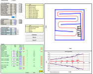
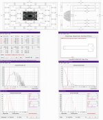
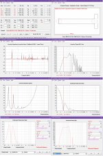
Well, here it is. I'm likely not going to progress this much further, as the results are, well, underwhelming. I've made the workbook available here as an attachment, just in case anyone wants to have a play with it. I've tried to model the TH-SPUD's layout as close as possible, using the Tang-Band W8-740P drivers with published specs and semi-inductance parameters derived from its impedance curve.
The biggest differences between the sim and the build is a slightly different location for the location of the drivers and without the expansion at the bottom to accommodate reversing one of the drivers (fiddling with the sim suggests that this only makes minor changes in the overall response.
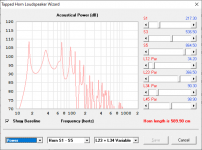
As you can see, the results don't look very impressive and this horn will definitely need to be damped.
Next up is perhaps a fold like the TH112's. That does look pretty interesting...
The biggest differences between the sim and the build is a slightly different location for the location of the drivers and without the expansion at the bottom to accommodate reversing one of the drivers (fiddling with the sim suggests that this only makes minor changes in the overall response.
As you can see, the results don't look very impressive and this horn will definitely need to be damped.
Next up is perhaps a fold like the TH112's. That does look pretty interesting...
Attachments

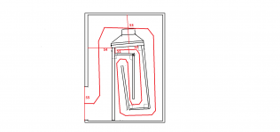
This is how I intend to look at the "TH112-like" fold. I've simplified the folding scheme a little (I don't think that it will make much difference) and I'm going to play with the dimensions a bit to make the top panel long enough to accommodate the entire driver. Same expansion throughout, except for the last section, which will be a constant expansion stub. Driver is actually going to be placed at S3 instead of S4.
Unlike my attempt at the TH-SPUD, which required the user to fiddle with two variables which adjusted S1 and S3, I'm guessing that this fold will require one variable to be fiddled with, and that will be most likely one that sets the desired ratio between S1 and S5.
Now, if only David could update Hornresp to include a TH option that would treat S4-S as a stub... 🙂.
Attachments
Hi, Brain
Hi, soho54
Hi, all
I´m currently working on a MLTL spreadsheet, which includes 5*180° and 3*90° bendings and therefore any error adds up quiet substantially. From what I read here the most reliable method is called ACM (advanced centreline method). But I wasen´t able to find some “readable” formulas on how to do so. Would be nice if someone could write it out (just fore one corner/bend).
Just from looking at the drawings I guess it would be:
90°ACM = 3 * 0,5 * S1 / tan(60°) When bends have parallel walls,
is there a better approach fore parallel walls?
Thanks a lot,
fore the research and ongoing support you tow offer.
Last edited:
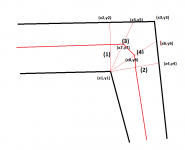
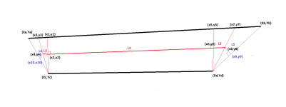
Here's how I do it (I've illustrated for a non-90 bend with non-parallel walls, because the technique words for this as well).
(1) determine and plot the first line orthogonal to the path going into the corner
(2) determine and plot the last line orthogonal to the path coming out of the corner.
(3) identify the intersection point for line #3 by the formula x5=(x2+x3)/2, y5=(y2+y3)/2 and plot it.
(4) identify the intersection point for line #4 by the formula x6=(x3+x4)/2, y6=(y3+y4)/2 and plot it.
(5) Identify the intersection point for the path going into the bend from x7=(x1+x5)/2,y7=(x1+y5)/2.
(6) Identify the intersection point for the path coming out of the bend the bend from x8=(x1+x5)/2,y8=(x1+y5)/2.
(7) Plot the path lines through the bend using the information above.
For bends that are not exactly 90 degrees, steps 1 and 2 are actually the most difficult steps, as you basically have to find the intersection of a line at an angle that's 1/2 the horn expansion angle from the corner to the outside panel. After you do those steps though, the rest is pretty easy.
Attachments
Line 6 should read:
(6) Identify the intersection point for the path coming out of the bend the bend from x8=(x1+x6)/2,y8=(x1+y6)/2.
(6) Identify the intersection point for the path coming out of the bend the bend from x8=(x1+x6)/2,y8=(x1+y6)/2.
Hmm, in describing the process, I think I "cracked" something I was trying to figure out for a long time - a "universal equation / process" for describing the path length along a horn consisting of straight sections that are folded. The only thing I need to do now is to confirm that my assumptions about the lines in blue are correct. If so, it should be a lot easier to determine the path length through a horn using Excel - just provide the coordinates for each panel, then apply the process 🙂. Something that it used to take me a day or two to figure out will now take minutes...
Attachments
Attachments
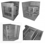
To take it further, use all 4 sides as the horn path. The bracing w00d hold the enclosure together. Talk about even loading on the driver! I could see that design easily being used for stepped or straight flare TH's.
STH1 TQWP 3ft Cube
I corrected the HR model to match the enclosure from 2 posts ago.
I matched the 2nd and 3rd segment volumes with the 2 internal enclosure volumes.
12" x 12" x 97.5" = 14,040in3 / 1,728in3 = 8.125ft3 x 28.317L = 230.076L.
34.5" x 34.5" x 9" = 10,712.25in3 / 1,728in3 = 6.2ft3 x 28.317L = 175.534L.
I corrected the HR model to match the enclosure from 2 posts ago.
I matched the 2nd and 3rd segment volumes with the 2 internal enclosure volumes.
12" x 12" x 97.5" = 14,040in3 / 1,728in3 = 8.125ft3 x 28.317L = 230.076L.
34.5" x 34.5" x 9" = 10,712.25in3 / 1,728in3 = 6.2ft3 x 28.317L = 175.534L.
Attachments
I am having trouble exporting and importing when trying to move from a folding spread sheet in excel to hornresp or the opposite. I am getting runtime error 9.
I am getting the results I want in hornresp, I then go to file and export. It then wants me to save the file. After saving and going to import on a spreadsheet I get the error. Any idea?
I am getting the results I want in hornresp, I then go to file and export. It then wants me to save the file. After saving and going to import on a spreadsheet I get the error. Any idea?
Can you post up a sample copy of a Hornresp file that's failing importation by the Excel workbook? Which workbook are you experiencing the problem with?I am having trouble exporting and importing when trying to move from a folding spread sheet in excel to hornresp or the opposite. I am getting runtime error 9.
I am getting the results I want in hornresp, I then go to file and export. It then wants me to save the file. After saving and going to import on a spreadsheet I get the error. Any idea?
im using windows 10I am new to using the program ive been messing with it for awhile now and just now even starting to think i can use it lol
ive been trying to use tham ss and mwth, i realize the horn simulated would be in a box thats crazy big and unrealistic but im just trying to get used to moving back and forth in the spread sheet and just learning it before i would make something serouis and take the time to build it
That's the wrong information to export from Hornresp into the BOXPLAN workbook. You want to export the parameters of the sim itself, which is done by selecting "File..Export..Hornresp Record".I am new to using the program ive been messing with it for awhile now and just now even starting to think i can use it lol
thats what I am doing. it then ask me to save it and then thats the file type it wants to save it as. I have tried to change the file type to several different things but it doesnt matter i still get the error.
If I am in the box plan work book and then i try to click export sim it gives me runtime error 76. it says path not found.
If I am in the box plan work book and then i try to click export sim it gives me runtime error 76. it says path not found.
- Home
- Loudspeakers
- Subwoofers
- Spreadsheet for Folded Horn Layouts...