Somebody asked in the Best midrange to pair with Beyma TPL-150 thread how to calculate directivity of a driver to match up with a horn. This question is being asked quite often and one I've spent some time trying to figure out for myself.
The often-quoted rule-of-thumb of "1,000,000 / Cone size in inches / dispersion in degrees = frequency in Hz" is a bit crude ,so I thought I'd share instead an Excel spreadsheet I've made for predicting beaming (without resorting to other software I cannot use at work...😉)
I started making the spreadsheet after reading posts on the subject by forum member @bolserst and doing some further research online. Eventually however, bolserst had to help me out with some of the equations before I could finalise it so all the credit goes to him really. He has also shown in posts on here that the predictions from the underlying equations match very well with actual measured driver directivity.
Hopefully the spreadsheet is simple enough to use but a few pointers:
(1) Download and change file extension from .asc to .xlsx;
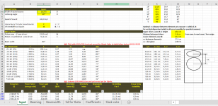
(2) make your inputs in cells C4 to C10;
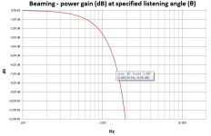
(3) Cell B24 will tell you at what frequency the response is down by -6dB at your specified listening angle;
(4) Cells G33 to G4035 will tell you the beamwidth of your specified size driver as a function of frequency. This can be useful for determining the upper crossover frequency to match the beamwidth of a horn (e.g. the 12P80Nd would match the 80 degrees BW of the TPL-150H at 1,420Hz on an infinite baffle);
(5) Cells H33 to H4035 will tell you what piston area (Sd) driver you would need to achieve your specified listening angle/beamwidth as a function of frequency (e.g. an Sd of 277 cm2 would have the same 80 degrees BW of the TPL-150H at 2,000Hz on an infinite baffle);
(6) Note the remarks in cells K18 andK34 about which info that is not (yet) valid for dipole (including 3, 4 and 5 above) and that I need to work more on (any help would be appreciated). Please note that data in cells A33:F4035 are correct for dipole however (as is graph on 'Beaming' tab) so easy enough to find the power loss as a function of frequency by scrolling down in the spreadsheet;
(7) There are three graphs on their own tabs. The X and Y axis ranges have been cropped to cover the most common type of usage but can be changed by the user if need be (the spreadsheet is unlocked);
(8) The two last tabs 'Coefficients' and 'Slask calc' should be left alone 😛;
Hopefully someone will find it useful. Any questions, suggestions, corrections, or improvements are more than welcome.
The often-quoted rule-of-thumb of "1,000,000 / Cone size in inches / dispersion in degrees = frequency in Hz" is a bit crude ,so I thought I'd share instead an Excel spreadsheet I've made for predicting beaming (without resorting to other software I cannot use at work...😉)
I started making the spreadsheet after reading posts on the subject by forum member @bolserst and doing some further research online. Eventually however, bolserst had to help me out with some of the equations before I could finalise it so all the credit goes to him really. He has also shown in posts on here that the predictions from the underlying equations match very well with actual measured driver directivity.
Hopefully the spreadsheet is simple enough to use but a few pointers:
(1) Download and change file extension from .asc to .xlsx;
(2) make your inputs in cells C4 to C10;
(3) Cell B24 will tell you at what frequency the response is down by -6dB at your specified listening angle;
(4) Cells G33 to G4035 will tell you the beamwidth of your specified size driver as a function of frequency. This can be useful for determining the upper crossover frequency to match the beamwidth of a horn (e.g. the 12P80Nd would match the 80 degrees BW of the TPL-150H at 1,420Hz on an infinite baffle);
(5) Cells H33 to H4035 will tell you what piston area (Sd) driver you would need to achieve your specified listening angle/beamwidth as a function of frequency (e.g. an Sd of 277 cm2 would have the same 80 degrees BW of the TPL-150H at 2,000Hz on an infinite baffle);
(6) Note the remarks in cells K18 andK34 about which info that is not (yet) valid for dipole (including 3, 4 and 5 above) and that I need to work more on (any help would be appreciated). Please note that data in cells A33:F4035 are correct for dipole however (as is graph on 'Beaming' tab) so easy enough to find the power loss as a function of frequency by scrolling down in the spreadsheet;
(7) There are three graphs on their own tabs. The X and Y axis ranges have been cropped to cover the most common type of usage but can be changed by the user if need be (the spreadsheet is unlocked);
(8) The two last tabs 'Coefficients' and 'Slask calc' should be left alone 😛;
Hopefully someone will find it useful. Any questions, suggestions, corrections, or improvements are more than welcome.
Attachments

Very nice spread sheet InOtin! 'Will come in handy. 🙂
Suggestion: On the first page, at the top right, one could insert a simple calculation for the cone diameter:
Element / sd, cm² / Cone Ø cm
18" 1218 39,4
15" 855 33,0
12" 531 26,0
10" 345 21,0
8" 220 16,7
6,5" 140 13,4
Usually, the "sd" is mentioned in manufacturers data sheets but seldom the moving cone's diameter, so by inserting manufacturers specified sd in the spread sheet, the cone diameter is calculated and can be written into cell C4.
Thank you InOtin for sharing this!! Will definitely adopt it.
Aadhoc1: you can also "goal seek" C13 to the desired Sd by changing C4.
Aadhoc1: you can also "goal seek" C13 to the desired Sd by changing C4.
Very nice spread sheet InOtin! 'Will come in handy. 🙂
Suggestion: On the first page, at the top right, one could insert a simple calculation for the cone diameter:
Element / sd, cm² / Cone Ø cm
18" 1218 39,4
15" 855 33,0
12" 531 26,0
10" 345 21,0
8" 220 16,7
6,5" 140 13,4
Usually, the "sd" is mentioned in manufacturers data sheets but seldom the moving cone's diameter, so by inserting manufacturers specified sd in the spread sheet, the cone diameter is calculated and can be written into cell C4.
@ LewinskiH01: Yes, I know. But I imagine the usual situation will be a person looking through and comparing data sheets from various manufacturers. Often the "sd" and the outer diameter of the basket is clearly written out, more seldom the actual outer diameter of the cone and the cone diameter can vary depending on the type of surround.
Lewinski,Thank you InOtin for sharing this!! Will definitely adopt it.
Aadhoc1: you can also "goal seek" C13 to the desired Sd by changing C4.
Unfortunately, Sd is not a reliable indicator of the dispersion of cone drivers other than in their piston range. At high frequencies, drivers usually radiate more HF from directly around the voice coil (voice coil size can vary quite a bit for the same size Sd), and cone breakup may result in multiple "virtual Sd" diameters at different frequencies.
Some drivers exhibit the uniformly narrowing directivity the spreadsheet would indicate, but the vast majority do not. To be sure the directivity is what you want requires measurement of the driver on the baffle, including any discrepancies such as are presented in the mounting depth and grill frame.
Art
So the larger the dust cap the lessier the driver can climb in the high... 3" voice coil for a 15" if you want a climby driver ?
The heavier the cone, the lesser the cone break modes... for free air with a 15" paper cone, mms > 100 g ? (I mean for a 15" linear in its piston band and above: > 450 Hz ?)
Dr Gedlle is for voice coil >= 4" for a 15" e.g. and better if heavy Mms (i believe he XO the Summa around 1K hz ?!)
The heavier the cone, the lesser the cone break modes... for free air with a 15" paper cone, mms > 100 g ? (I mean for a 15" linear in its piston band and above: > 450 Hz ?)
Dr Gedlle is for voice coil >= 4" for a 15" e.g. and better if heavy Mms (i believe he XO the Summa around 1K hz ?!)
Dust caps may be much larger than the voice coil. The difference in size will affect breakup mode frequency and dispersion, as does the stiffness.So the larger the dust cap the lessier the driver can climb in the high... 3" voice coil for a 15" if you want a climby driver ?
The heavier the cone, the lesser the cone break modes... for free air with a 15" paper cone, mms > 100 g ? (I mean for a 15" linear in its piston band and above: > 450 Hz ?)
Any calculator assuming a cone behaves like a perfect piston will only be correct for a perfect piston, and there are no real cones that behave as a perfect piston. Some are considerably better than others, but you must look at actual measurements to see how they differ.
few are showing lists with measurements like you did with compression drivers in an other thread 🙂
Hi !
Tried to use this calculator to find out where to cross TPL-150H with a B&C 8PE21 midrange.
I am using Minidsp OpenDRC with Firdesigner to design linear phase crossovers.
I am trying to avoid the distortion centered at 1.8khz in the TPL as much as i can and at the same time try to match the directivity at 80deg for the B&C 8PE21 and TPL.
I know that i would be better off with a 6.5" midrange, but i hope the results in directivity matching could be satisfying.
Can anyone precisely let me know where the 8PE21 reach 80degrees?
c4 16,735
c13 220,0
- Status
- Not open for further replies.
- Home
- Loudspeakers
- Multi-Way
- Spreadsheet for calculating driver beaming / directivity / dispersion / beamwidth