Typical 3-way line arrays get pretty wide due to all the drivers. Would separating the woofers into a separate array, adjacent to the mid-tweeter array (see attached) increase the frequency of the dipole peak of the woofers? (this is an OB array)
Another way of asking this: Is a narrow gap is all that's necessary for phase cancellation? Thanks!
Another way of asking this: Is a narrow gap is all that's necessary for phase cancellation? Thanks!
Attachments
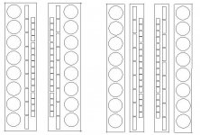
Depends on frequency and gap placement but in most cases, including this one, the peak position's dominated by the distance to the nearest edge. So I wouldn't expect the woofer peak to budge much, though directivity might improve a bit with the gap above 500Hz or so where the wavelengths get short enough for the gap to start affecting the near field. A microphone sweep in Edge will give you the details.
Where baffle width matters the most will be in the Neo3 and Neo8 lines (to hazard a guess based on the driver outlines 😛) so, in my opinion, you're probably better off focusing on running them near-nude with the tightest horizontal spacing you can manage which still has enough of a gap between the 'netostat lines for good Neo3 directivity. If I had a listening space big enough for line arrays I would kick off the design with a single line of alternating Neo3s and Neo8s rather than the paired lines shown here and see if that would do the job---more consistent horizontal directivty at the ~1.5kHz cross between the Neos that way.
Where baffle width matters the most will be in the Neo3 and Neo8 lines (to hazard a guess based on the driver outlines 😛) so, in my opinion, you're probably better off focusing on running them near-nude with the tightest horizontal spacing you can manage which still has enough of a gap between the 'netostat lines for good Neo3 directivity. If I had a listening space big enough for line arrays I would kick off the design with a single line of alternating Neo3s and Neo8s rather than the paired lines shown here and see if that would do the job---more consistent horizontal directivty at the ~1.5kHz cross between the Neos that way.
Last edited:
Thanks for the info. Ran some sims in edge as suggested.
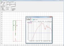
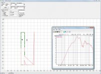
I compared the effect of woofers on the edge of a very large baffle, to woofers near another large panel (approximately, since edge doesn't have capability for multiple baffles). Seen in largebaffle.jpg vs splitbaffle.jpg
Greatest changes were at low frequencies, with little shift in the dipole peak.
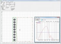
I repeated this with a smaller mid-tweet baffle about the size of the neo8+neo3 array. Again, very little effect on the woofer dipole peak with with separating the woofer array.
All measurements were at 3m and slightly off axis. This does suggest the effects (if any will be strongest for mid/tweets). Those results to follow.
I compared the effect of woofers on the edge of a very large baffle, to woofers near another large panel (approximately, since edge doesn't have capability for multiple baffles). Seen in largebaffle.jpg vs splitbaffle.jpg
Greatest changes were at low frequencies, with little shift in the dipole peak.
I repeated this with a smaller mid-tweet baffle about the size of the neo8+neo3 array. Again, very little effect on the woofer dipole peak with with separating the woofer array.
All measurements were at 3m and slightly off axis. This does suggest the effects (if any will be strongest for mid/tweets). Those results to follow.
Attachments
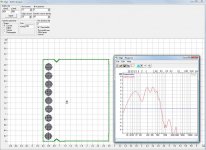
Looking at effects of a gap between panels on high frequency response:
Comparing first two images indicates (according to edge) that leaving a gap between panels is effective for dipole cancellation at high frequencies.
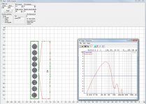
third image - combining the panels results in primarily low-frequency gain.
I didn't show results for arrays, because it seems edge is over-estimating comb-filtering, at least as I had set things up.
Comparing first two images indicates (according to edge) that leaving a gap between panels is effective for dipole cancellation at high frequencies.
third image - combining the panels results in primarily low-frequency gain.
I didn't show results for arrays, because it seems edge is over-estimating comb-filtering, at least as I had set things up.
Attachments

The baffle's only modeled where the green squares are so I wouldn't put much weight on this data. Looks like what's needed for good edge density is an equal number of drivers on each part of the baffle. Unfortunately that's a symmetric configuration so it'll provide information about behavior at the crossover frequencies but isn't so useful elsewhere. Combined with individual simulations of each line that's probably enough data to get a decent sense of how the build would behave.
But now that I'm reminded about Edge's edge source fill behavior simming this is more complicated than I was thinking in my previous post. It should be possible to use superposition of different sims to figure out the gap effects. The place I'd start with that would 1) sim a baffle the width you intend to build, 2) sim a baffle that reaches all the way across the gap to edge of the next baffle over, 3) sim a baffle that reaches to the far side of the gap, 4) export all the data and see if 1 - 2 + 3 makes sense. I just threw that together in Edge and it looks reasonable---the antibaffle of 3 knocks out most of the boost from 2 around the dipole peak but a dB but the second baffle contributes a dB or so of gain at lower frequencies where the wavelegth's too large for the wavefront to bend over and hit the gap.
But now that I'm reminded about Edge's edge source fill behavior simming this is more complicated than I was thinking in my previous post. It should be possible to use superposition of different sims to figure out the gap effects. The place I'd start with that would 1) sim a baffle the width you intend to build, 2) sim a baffle that reaches all the way across the gap to edge of the next baffle over, 3) sim a baffle that reaches to the far side of the gap, 4) export all the data and see if 1 - 2 + 3 makes sense. I just threw that together in Edge and it looks reasonable---the antibaffle of 3 knocks out most of the boost from 2 around the dipole peak but a dB but the second baffle contributes a dB or so of gain at lower frequencies where the wavelegth's too large for the wavefront to bend over and hit the gap.
Last edited:
Yeah... I simulated it with many more points sampled around the perimeter and it didn't make much difference, so I cut back to speed up the sims.
I think this may call for some actual on- and off-axis measurements of a neo3 on a narrow baffle with and without a large panel close to it.
I think this may call for some actual on- and off-axis measurements of a neo3 on a narrow baffle with and without a large panel close to it.
Just edited my post; I suspect that method will get you close. Agree confirming with measurement before committing to a full build would be wise.
- Status
- Not open for further replies.
- Home
- Loudspeakers
- Multi-Way
- Splitting line array into sections for dipole cancelation?