try this link
http://waltjung.org/PDFs/A_High_Accuracy_Inverse_RIAA_Network.pdf
or http://www.hagtech.com/pdf/riaa.pdf
regards
bob
http://waltjung.org/PDFs/A_High_Accuracy_Inverse_RIAA_Network.pdf
or http://www.hagtech.com/pdf/riaa.pdf
regards
bob
I use LTSpice, but, being a novice with spice, I have not found out how to incorporate a laplace transform.
I have, however, found the corresponding formula that I searched:
http://www.diyaudio.com/forums/showthread.php?postid=849619#post849619
thanks,
Rüdiger
I have, however, found the corresponding formula that I searched:
http://www.diyaudio.com/forums/showthread.php?postid=849619#post849619
thanks,
Rüdiger
Marshall Leach has an article using SPICE and the LAPLACE transform -- the article deals with horn loudspeakers but from it you should be able to glean how to incorporate the LAPLACE function.
http://users.ece.gatech.edu/~mleach/papers/hornmod.pdf
http://users.ece.gatech.edu/~mleach/papers/hornmod.pdf
Hi,
I am not familiar with LT-Spice (I am using Microcap 7) but the generic PSpice syntax is:
LAPLACE:
E|G{name} {+node} {-node} LAPLACE {expression} {s expression}
Example:
E_LOPASS 4 0 LAPLACE {V(1)} {10 / (s/6800 + 1)}
So if your Pspice version does not provide a dependant Laplace source as a schematic entry you can make a sub circuit yourself for the Laplace expression and put it in your library.
A good link for Pspice syntax:
http://www.ecircuitcenter.com/SPICEsummary.htm at http://www.ecircuitcenter.com
Cheers")
I am not familiar with LT-Spice (I am using Microcap 7) but the generic PSpice syntax is:
LAPLACE:
E|G{name} {+node} {-node} LAPLACE {expression} {s expression}
Example:
E_LOPASS 4 0 LAPLACE {V(1)} {10 / (s/6800 + 1)}
So if your Pspice version does not provide a dependant Laplace source as a schematic entry you can make a sub circuit yourself for the Laplace expression and put it in your library.
A good link for Pspice syntax:
http://www.ecircuitcenter.com/SPICEsummary.htm at http://www.ecircuitcenter.com
Cheers
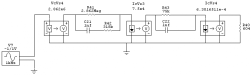
...........theoritical inverse riaa...........
Or just RIAA .
BeigeBag Software A/D V4.x and higher can do this.
The equations can be included in the voltage source or at the output of the circuit . Eliminates any errors that real world components can cause.
Look for "resources " at www.beigebag.com
There is an RIAA example with all details and examples that yoiu can run.
You can also download a free time limited version of A/D V4.x and
run the simulations yourself. Very easy after the first try.
Cheers,
Ashok.
Hi,
I'm lost. The formula as spice command:
E_RIAA In Out LAPLACE {V(Out)}={(1+0.00318*S)*((1+0.000075*S)/(1+0.000318*S))}
does something, but it's wrong and I don't know what happens.
If someone could confirm whether the formula in itself is senseless or should work at all?
The nodes 'in' and 'out' are just that...
Rüdiger

Did you check the "resources tab" at the Beige Bag web site ?
www.beigebag.com
The formula is given in that article about the RIAA correction.
Application might be slightly different in that GUI but you get the idea.
www.beigebag.com
The formula is given in that article about the RIAA correction.
Application might be slightly different in that GUI but you get the idea.
Hi Rudiger,
In plain pspice text as a sub circuit this works for me:
.SUBCKT I_RIAA IN OUT PARAMS: tau_1=3180u tau_2=318u tau_3=75u
+tau_4=3.18u
*
E1 OUT 0 LAPLACE {V(IN)}={(1+tau_1*S)*(1+tau_3*S)
+/((1+tau_2*S)*(1+tau_4*S))}
R1 OUT 0 1meg
*
.ENDS
For a normal invers RIAA make tau_4=0 and for a corrected RIAA incorporating the 3.16 us time constant, make tau_4=3.18u
Maybe that works in your pspice?
Cheers
Onvinyl said:E_RIAA out 0 LAPLACE {1117*V(in)}={(1+0.00318*S)*((1+0.000075*S)/(1+0.000318*S))}
The plus for extending the expression on the next line is missing. It must be:
E_RIAA out 0 LAPLACE +{1117*V(in)}={(1+0.00318*S)*(1+0.000075*S)/(1+0.000318*S)}
Btw. Why that factor "1117"?
Pjotr said:
The plus for extending the expression on the next line is missing. It must be:
E_RIAA out 0 LAPLACE +{1117*V(in)}={(1+0.00318*S)*((1+0.000075*S)/(1+0.000318*S))}
Pjotr,
there is no next line. however, the expression computes without error warning, but shows strange behaviour. This is not related to the gain modifier (1117*)
I give up for today,
Rüdiger
Hi,
That sub circuit should work in any standard pspice compliant simulator. Since we are most time interested in the gain at 1 kHz I have modified the model so it gives 0 dB gain at 1 kHz:
.SUBCKT I_RIAA IN OUT PARAMS: tau_1=3180u tau_2=318u
+tau_3=75u tau_4=3.18u CORR=9.897
E1 OUT 0 LAPLACE {V(IN)}={(1+tau_1*S)*(1+tau_3*S)
+/((1+tau_2*S)*(1+tau_4*S)*CORR)}
R1 OUT 0 1meg
.ENDS
Cheers
Attachments
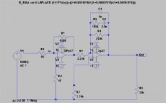
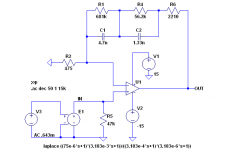
Here's an LTSpice example of Laplace for inverse RIAA. This inverse RIAA includes the "Neumann" 3.18us or 50kHz lead in addition to the usual 50/2122Hz lags and 500Hz lead. The laplace works well in LTSpice only for AC analysis, for transient analysis you should use an RC network. Of course you need the RC network or a test record for frequency response verification if you built something.
The example uses the "El Cheapo" feedback network with an ideal 1-pole opamp, results are similar to OPA637 model.
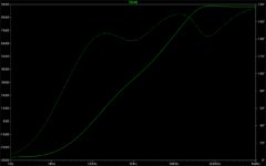
I have built and tested frequency response of both tube and solidstate phono preamps modeled in LTSpice, agreement between simulation and measurement from 100Hz and 10kHz normalized at 1kHz is usually within 0.2dB, 0.7 to 1dB from 20Hz to 20kHz. I doubt it is possible to verify frequency response this closely with a test record and phono cartridge, if you have done this please let me know.
The E source with the Laplace formula used adds 19.9dB gain at 1kHz, so for 5mV on the preamp input the AC source (V3 in this example) should be 505.8uV.
The example circuit for Laplace:
The example uses the "El Cheapo" feedback network with an ideal 1-pole opamp, results are similar to OPA637 model.
I have built and tested frequency response of both tube and solidstate phono preamps modeled in LTSpice, agreement between simulation and measurement from 100Hz and 10kHz normalized at 1kHz is usually within 0.2dB, 0.7 to 1dB from 20Hz to 20kHz. I doubt it is possible to verify frequency response this closely with a test record and phono cartridge, if you have done this please let me know.
The E source with the Laplace formula used adds 19.9dB gain at 1kHz, so for 5mV on the preamp input the AC source (V3 in this example) should be 505.8uV.
The example circuit for Laplace:
Attachments
- Status
- This old topic is closed. If you want to reopen this topic, contact a moderator using the "Report Post" button.
- Home
- Source & Line
- Analog Line Level
- SPICE transfer function for RIAA testing