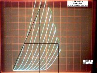
Some more GU50 triode curves. Modified pentode too.
http://www.diyaudio.com/forums/tubes-valves/160240-suppresor-grid-used-feedback-3.html#post2071537
I controlled for several characteristics GU50 tube in triode mode (G3 to K), of different curve tracer pictures.
All are fairly similar except for Smoking-amp testing.
With its curves MU = 5.95 and ra = 1.2 Kohm. See atach. Much different than the others (MU =< 5; ra = 930-955 ohm.)
Is that the tracer makes mistakes?
Attachments
New topic started here: Oh No! Another Pentode Model
I get an error message when I try the link. It says it can not find it and to contact an administrator.
Curves look interesting.
"Is that the tracer makes mistakes?"
I had installed a variable (and extended range) gain control for the "g1" step size on the side of the tracer, so it is quite possible it was not in the calibrate position for those traces. The tracer has never been calibrated in general since I bought it, and fixed it up, but some simple testing showed the axis measurements were reasonably in the ball park. Then again, there are a lot of scale factors selectable for each axis, and I didn't test them all. YRMV
The step power supply (and the step amplifier) were modified to obtain the higher grid voltages needed for tube testing (versus the Mosfets it was intended for). The variable gain control typically has to be set 2X or 3X above the nominal front panel knob's range, for use as tube g1 step voltages. Might have affected calibration some, or it wasn't set at exactly 2X maybe.
I usually just adjust the V step gain control so the curve set fills the screen nicely. (there is a variable "g1" V offset control too.) I may have forgotten to re-measure the step size. (the scope provides for measuring the step size as a dot pattern on the horizontal axis.)
Last edited:
I get an error message when I try the link. It says it can not find it and to contact an administrator.
Curves look interesting.
It got merged into the Spice model sticky:
http://www.diyaudio.com/forums/tubes-valves/243950-vacuum-tube-spice-models-3.html
"Is that the tracer makes mistakes?"
I had installed a variable (and extended range) gain control for the "g1" step size on the side of the tracer, so it is quite possible it was not in the calibrate position for those traces. The tracer has never been calibrated in general since I bought it, and fixed it up, but some simple testing showed the axis measurements were reasonably in the ball park. Then again, there are a lot of scale factors selectable for each axis, and I didn't test them all. YRMV
The step power supply (and the step amplifier) were modified to obtain the higher grid voltages needed for tube testing (versus the Mosfets it was intended for). The variable gain control typically has to be set 2X or 3X above the nominal front panel knob's range, for use as tube g1 step voltages. Might have affected calibration some, or it wasn't set at exactly 2X maybe.
I usually just adjust the V step gain control so the curve set fills the screen nicely. (there is a variable "g1" V offset control too.) I may have forgotten to re-measure the step size. (the scope provides for measuring the step size as a dot pattern on the horizontal axis.)
Yes, I understand.
I have not seen tracer very long time. But remember inadequate results due to calibration.
Best diying.
- Status
- Not open for further replies.