Audiophilenoob said:whatever stuff you guys are on that hear differences is cables... I want some 😛 😀
Agreed the only time I've really noticed a clear difference was with subs.
Out of interest I used some really poor and very thin telephone type cable. Against a thick solid core copper mains cable.
I think its easy enough to say which sounded the better cable. The thin stuff wasn't as clean as the solid core.
What do you think this whole discussion is about? Maybe you were not able to hear any differences but many and I would say most do hear a difference in systems that are less than optimum or at a point of seriously diminished returns...auplater said:rnrss wrote..
I agree with Johann... traditional damping factor is pretty much useless.
I'd stick to using your ears, I think,... your math seems a bit suspect...and your argumentation a bit patronizing Not much definitive proof offered supporting the opposite thesis has yet been presented.... nor any concerning "wire" sound...
How much definitive support do you want? Since you are not willing ot support your claims with math or test results and feel it should all be judged strictly by "your" ears what do you want from me, cut my ears off, give them to you so you can put them on your head so you can have your definitive proof? Others on here, in fact I would hazzard a guess that most others on here can hear the difference and from my tests the difference happens to correspond reasonably with the math... if you care to do anything constructive in this conversation beyond giving it lip service show us your data or whatever you have to support your claim.
Just because you are unable to understand why you hear no difference in your testing is hardly a reason to dismiss it as bs...
Secondly if you feel my math is suspect, for the sake of accuracy, do this forum and me a favor and CORRECT IT!! Show us your stuff man! So many people on here just spout out with nothing whatsoever to back them up... (not even math), and as far as I am concerned spouting is all you have contributed to this conversation since I joined it... so do something about it man and correct all my errors as it will be for everyones best interest and I for one gladly accept that...
I presented the damping factor formula as my proof that what I heard was not just fanciful listening... I used the math as a means of checking on myself so I keep it real... The rest is all in a persons abilities/capabilities to hear and the characteristics of their system, not much I or anyone else can prove one way or the other about your ears, what you hear and what you dont...
All I can say is that others have heard the difference good damping makes and I also have heard the differences, and I am very sorry that you are unable to enjoy the benefits of quality damping like the rest of us but that is no reason to throw the baby out with the wash water...
auplater said:
rnrss wrote...
Have you ever heard a good horn setup? I am not sure how to describe it exactly but I will give it my best shot...
________________
Yup... they all have ... how shall I say it... a horn-ey character that makes the music and image sound not quite right... don't get me wrong.. they are efficient, big and dog-ugly... not to my taste... reminds me of the sound from the old Victrolas etc... I even built a dozen or so folded horns 30 years ago using big EV drivers for concert halls and frat parties.... old technology that to my taste hasn't withstood the test of time...(i know.. SET amps and horns are all the rage in certain circles, so caveat emptor, ymmv, etc.)
Now in my original post I talked about the good points of a planar driver as I did not want it to go here... but now that this conversation has gone into character of sound then its fair game to talk about planar character as well... Dont get me wrong I can rattle off all the issues horns have too, but since you built them and are an expert on "horn-ey" sound I will save that for you to rattle off and I will stick to the planars characteristics or lack of....
First off I said a "GOOD" horn setup ok... and "ALL" is a very poor choice in words because that includes my rig and my rig does not have that horn-ey sound you are talking about... and mine is also a razor sharp wall of music in front of me that has a nearly perfect side to side and top to bottom image, so I cant imagine what your issues are with the image from a "good" horn setup?
Oh BTW I have a planar ribbon midrange in my hand right now... I saved one for kicks... I have always been fascinated with them...
In fact I did several tests on them when I was considering it for a midrange driver for my Quad amp'd hart system...
What I did not like about their character is lets say how beamy they are... very narrow, and as I switched different mic's to the RTA while playing pink noise and then did the same test comparing it to the altec 511b horn I found that the 511b had considerably greater horizontal dispersion to my surprize...
That I did not expect.
Then when doing the vertical tests I found that the planar mid had super narrow vertical dispersion... (that is why they stack them 6feet high)... Once again to my surprise the horn did considerably better than expected...
So to be fair to them and myself I hooked them up, pulled the midrange hart out and I have a 4 section stereo fully adjustable 20-20k crossover, (with ten turn pots for adjustment), so put it in line, threw these things in boxes set up the crossovers and played some music through it...
This was a quad amp system so the first thing I had to do was to crank the planar amp volume way up to get them to match the same loudness as rest of the drivers which were only 90db @1watt speakers anyway... so they are considerably less efficient than the cone speakers I replaced with them and when used side by side so they required considerable more power to drive to the same levels as one cone driver I previously had in there...
The next thing I noticed is that the sound image seemed to shift to different points on the vertical axis as the tones went up and down the scale and I thought that was sort of strange... so upon investigating this phenomena with a sweeping tone generator I could physically see the driver set up nodes on the film and these nodes would walk up and down the speaker film, (the film would be to a planar the same as a cone would be on a cone speaker), and when you give it a little volume you could actually see the film form lumps and shift from side to side and up and down... so it caused little hot spots to go mostly up and down and I found that to be a very unrealistic image...
It very much reminded me of what I did when I was a kid when I stretched a peice of plastic wrap across a speaker and glued a little mirror in the center to make a laser light show... The planar diaphram looked exactly like the plastic wrap and the speaker made it form nodes if any of you have tried this as a kid...
So all things considered out they went... and the harts went back in...
That was a fun system, I still have the drivers, a pair of 24" subs that shook not only my house but the neighbors too LOL 4 - 10"midbass, 2 - 7" midtweets and a pair of jbl 2426j's mounted on an altec 511b horny...
That and if the horns you built sounded horney as you put it then that sort of says something about your design and setup doesnt it?
Mine do not, especially those bigg butts do not... The fact that they do not is one point people comment on all the time concerning the way the systems I posted sound...
So in a nutshell I found planars to be very inefficient, they do not provide a stable vertical image, they are significantly more beamy horizontally than cones or even some good horns, since they are so inefficient they have little dynamic range so lower notes on instruments do not sound real and drums did not tickle my nose, the higher notes above say 2500 sound good and for someone like me who likes concert level tunes, they severely distorted when I cranked them up trying to hit the 110db mark... Then lastly the system that I auditioned at one of the local high end shops had extremely thin bass and midbass... and I like a drum to sound like a drum and have the same impact as a real drum...
On the plus side they are crystal clear as long as you keep the volumes reasonably low...
I am not in love with my system and yup they are one ugly mutha and ironically the chicks love em lol, but if someone can come up with something that is over all better for my needs I would dump it and jump on your bandwagon in a new york sec and you new yorkers know how fast that is!! lol
As far as I am concerned much of the so called new technology, especially concerning speakers is more for the fad followers than has any "real" improvement in sound reproduction...
But hey planars make your day and suit your needs and you are happy with them that is all that counts in the end and then I am happy that you are happy...
Anyway I am a equal opportunity nit picker and if anyone wants to hear me gripe about all the things I do not like about my horns or horns in general just ask and I will happy to gripe about them too LOL
Mike, rcw brought up an excellent point that skipped my mind when going over this in previous posts and I had the more ideal situation in mind...
Personally, I wind my own coils or contract a local transformer company to wind them for me in the case of that monster coil that I use... they were a cheap 75 bucks each and when compared to buying another amp I felt they were a bargin...
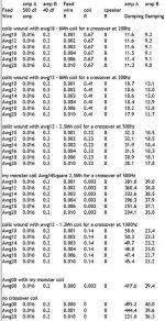
Mike I dont know where your speaker is crossed over but I did a quick spreadsheet and plunked in 3 popular crossover values hopefully to help you to better decide if its worth the expense of an upgrade...
I used the resitance values of the 12 gauge coils that you can get from madisound.com... and the chart will show you the difference in damping with the crossover coil included in the circuit..
Madisound will also measure your existing coil and wind new ones to match them with larger wire should you wish to go that route to lower your series R...
I assume one of these would be close to what you have and if your speaker has say awg18 in the coils you could always replace it too for a few extra bucks with the awg12 coils... or wind your own even larger coils...
I picked crossovers of 200, 500, and 1000, and used rated amp damping of 500 and then 40 as you have now...
amp A amp B Feed amp A amp B
Feed 500 df 40 df wire coil speaker
Wire amp R R R Damping Damping
coils wound with awg18 - 6Mh coil for a crossover at 200hz
Awg10 0.016 0.2 0.001 0.67 8 11.6 9.2
Awg12 0.016 0.2 0.002 0.67 8 11.6 9.2
Awg14 0.016 0.2 0.003 0.67 8 11.6 9.1
Awg16 0.016 0.2 0.004 0.67 8 11.5 9.1
Awg18 0.016 0.2 0.006 0.67 8 11.4 9.1
Awg20 0.016 0.2 0.010 0.67 8 11.3 9.0
coils wound with awg12 - 6Mh coil for a crossover at 200hz
Awg10 0.016 0.2 0.001 0.41 8 18.7 13.1
Awg12 0.016 0.2 0.002 0.41 8 18.6 13.0
Awg14 0.016 0.2 0.003 0.41 8 18.6 13.0
Awg16 0.016 0.2 0.004 0.41 8 18.4 12.9
Awg18 0.016 0.2 0.006 0.41 8 18.2 12.8
Awg20 0.016 0.2 0.010 0.41 8 17.9 12.7
coils wound with awg12 - 2.5Mh coil for a crossover at 500hz
Awg10 0.016 0.2 0.001 0.23 8 32.3 18.5
Awg12 0.016 0.2 0.002 0.23 8 32.1 18.5
Awg14 0.016 0.2 0.003 0.23 8 31.9 18.4
Awg16 0.016 0.2 0.004 0.23 8 31.5 18.3
Awg18 0.016 0.2 0.006 0.23 8 30.9 18.1
Awg20 0.016 0.2 0.010 0.23 8 30.1 17.8
my monster coil Awg#4Square 2.5Mh for a crossover of 500Hz
Awg10 0.016 0.2 0.001 0.003 8 381.0 39.0
Awg12 0.016 0.2 0.002 0.003 8 360.4 38.8
Awg14 0.016 0.2 0.003 0.003 8 332.6 38.5
Awg16 0.016 0.2 0.004 0.003 8 296.3 37.9
Awg18 0.016 0.2 0.006 0.003 8 251.6 37.1
Awg20 0.016 0.2 0.010 0.003 8 204.1 35.8
coils wound with awg12 - 1.2Mh coil for a crossover at 1000hz
Awg10 0.016 0.2 0.001 0.14 8 50.6 23.4
Awg12 0.016 0.2 0.002 0.14 8 50.3 23.3
Awg14 0.016 0.2 0.003 0.14 8 49.7 23.2
Awg16 0.016 0.2 0.004 0.14 8 48.8 23.0
Awg18 0.016 0.2 0.006 0.14 8 47.4 22.7
Awg20 0.016 0.2 0.010 0.14 8 45.4 22.2
Awg00 with my monster coil
Awg00 0.016 0.2 0.000 0.003 8 417.6 39.4
no crossover coil
Awg00 0.016 0.2 0.000 0 8 495.2 40.0
Awg10 0.016 0.2 0.001 0 8 444.4 39.6
Awg20 0.016 0.2 0.010 0 8 221.0 36.3
When comparing a typical coil to the no coil scenario you can see by the table that we approach the point of diminishing returns rather quickly with a series crossover coil wound with small wire placed in line with the driver as rcw is pointing out... I cant classify it as a fallacy exactly as people can hear even small improvements but the returns really start to diminish with coils wound with small wire...
You can also see that my monster wire + monster coil vs the no coil case really keeps the damping up there nicely... Resulting in 85% of the amplifiers maximum dampening ability to be applied to the system using the monster coil with an awg00 wire...
So it seems to me that when you make your decision to buy or not to buy, you will need to gauge what you heard when you changed from the wire you had to the number 14 wire you have now.
I made this table for you and others who are interested, so you can use it to get a feeling for how much improvement you can expect from more upgrades... The one thing I think that it will illustrate is that it takes very little improvement in damping to get a considerably noticable improvement in sound...
Knowing your components and values of your coils are also very important so you can determine how close to the point of diminishing returns you are if at all...
I threw this table together because I dont want my exuberant approach to damping to mislead anyone and especially since I did not include it in my calculation when mentioning what buying a 500df amp would do for your system...
I hope this helps put everything into a more useful perspective for you... and helps you to make a good educated guess on what to expect when comparing the differences you heard from the wire changes you made so far and any future changes you hope to make...
I dont think this table will look right so just in case I took a pic of it to help with that and included it with the post...
Personally, I wind my own coils or contract a local transformer company to wind them for me in the case of that monster coil that I use... they were a cheap 75 bucks each and when compared to buying another amp I felt they were a bargin...
Mike I dont know where your speaker is crossed over but I did a quick spreadsheet and plunked in 3 popular crossover values hopefully to help you to better decide if its worth the expense of an upgrade...
I used the resitance values of the 12 gauge coils that you can get from madisound.com... and the chart will show you the difference in damping with the crossover coil included in the circuit..
Madisound will also measure your existing coil and wind new ones to match them with larger wire should you wish to go that route to lower your series R...
I assume one of these would be close to what you have and if your speaker has say awg18 in the coils you could always replace it too for a few extra bucks with the awg12 coils... or wind your own even larger coils...
I picked crossovers of 200, 500, and 1000, and used rated amp damping of 500 and then 40 as you have now...
amp A amp B Feed amp A amp B
Feed 500 df 40 df wire coil speaker
Wire amp R R R Damping Damping
coils wound with awg18 - 6Mh coil for a crossover at 200hz
Awg10 0.016 0.2 0.001 0.67 8 11.6 9.2
Awg12 0.016 0.2 0.002 0.67 8 11.6 9.2
Awg14 0.016 0.2 0.003 0.67 8 11.6 9.1
Awg16 0.016 0.2 0.004 0.67 8 11.5 9.1
Awg18 0.016 0.2 0.006 0.67 8 11.4 9.1
Awg20 0.016 0.2 0.010 0.67 8 11.3 9.0
coils wound with awg12 - 6Mh coil for a crossover at 200hz
Awg10 0.016 0.2 0.001 0.41 8 18.7 13.1
Awg12 0.016 0.2 0.002 0.41 8 18.6 13.0
Awg14 0.016 0.2 0.003 0.41 8 18.6 13.0
Awg16 0.016 0.2 0.004 0.41 8 18.4 12.9
Awg18 0.016 0.2 0.006 0.41 8 18.2 12.8
Awg20 0.016 0.2 0.010 0.41 8 17.9 12.7
coils wound with awg12 - 2.5Mh coil for a crossover at 500hz
Awg10 0.016 0.2 0.001 0.23 8 32.3 18.5
Awg12 0.016 0.2 0.002 0.23 8 32.1 18.5
Awg14 0.016 0.2 0.003 0.23 8 31.9 18.4
Awg16 0.016 0.2 0.004 0.23 8 31.5 18.3
Awg18 0.016 0.2 0.006 0.23 8 30.9 18.1
Awg20 0.016 0.2 0.010 0.23 8 30.1 17.8
my monster coil Awg#4Square 2.5Mh for a crossover of 500Hz
Awg10 0.016 0.2 0.001 0.003 8 381.0 39.0
Awg12 0.016 0.2 0.002 0.003 8 360.4 38.8
Awg14 0.016 0.2 0.003 0.003 8 332.6 38.5
Awg16 0.016 0.2 0.004 0.003 8 296.3 37.9
Awg18 0.016 0.2 0.006 0.003 8 251.6 37.1
Awg20 0.016 0.2 0.010 0.003 8 204.1 35.8
coils wound with awg12 - 1.2Mh coil for a crossover at 1000hz
Awg10 0.016 0.2 0.001 0.14 8 50.6 23.4
Awg12 0.016 0.2 0.002 0.14 8 50.3 23.3
Awg14 0.016 0.2 0.003 0.14 8 49.7 23.2
Awg16 0.016 0.2 0.004 0.14 8 48.8 23.0
Awg18 0.016 0.2 0.006 0.14 8 47.4 22.7
Awg20 0.016 0.2 0.010 0.14 8 45.4 22.2
Awg00 with my monster coil
Awg00 0.016 0.2 0.000 0.003 8 417.6 39.4
no crossover coil
Awg00 0.016 0.2 0.000 0 8 495.2 40.0
Awg10 0.016 0.2 0.001 0 8 444.4 39.6
Awg20 0.016 0.2 0.010 0 8 221.0 36.3
When comparing a typical coil to the no coil scenario you can see by the table that we approach the point of diminishing returns rather quickly with a series crossover coil wound with small wire placed in line with the driver as rcw is pointing out... I cant classify it as a fallacy exactly as people can hear even small improvements but the returns really start to diminish with coils wound with small wire...
You can also see that my monster wire + monster coil vs the no coil case really keeps the damping up there nicely... Resulting in 85% of the amplifiers maximum dampening ability to be applied to the system using the monster coil with an awg00 wire...
So it seems to me that when you make your decision to buy or not to buy, you will need to gauge what you heard when you changed from the wire you had to the number 14 wire you have now.
I made this table for you and others who are interested, so you can use it to get a feeling for how much improvement you can expect from more upgrades... The one thing I think that it will illustrate is that it takes very little improvement in damping to get a considerably noticable improvement in sound...
Knowing your components and values of your coils are also very important so you can determine how close to the point of diminishing returns you are if at all...
I threw this table together because I dont want my exuberant approach to damping to mislead anyone and especially since I did not include it in my calculation when mentioning what buying a 500df amp would do for your system...
I hope this helps put everything into a more useful perspective for you... and helps you to make a good educated guess on what to expect when comparing the differences you heard from the wire changes you made so far and any future changes you hope to make...
I dont think this table will look right so just in case I took a pic of it to help with that and included it with the post...
Attachments
rnrss said:
For a damping factor of 30 that comes to an internal Z of .27ohms into an 8ohm load
For a nominal 8ohm driver circuit current is:
2.37amps = sqrt{45watts/8ohms}
soongsc said:
Back EMF is generated from the inertia of the cone and natural response of the suspension bringing the cone back to neutral position. So it cannot be derived from the 45 Watts used to drive the driver, but must be caluculated based on the speed at which the cone is travelling and the magnetic field density.
Well as you can see I just did it!
What I did in that little exercize is most commonly called reverse engineering for lack of a better term... That is when you start at the end or finished product and work your way back to the beginning...
If you want to make an exacting mathematical model that takes in everything known to man in your calculations starting from the driver to the amp, by all means post it and I will be happy to show you how to reverse calculate it ok...
But then I already did that within the boundaries of a "close enough" for government work 😉
Audiophilenoob said:whatever stuff you guys are on that hear differences is cables... I want some 😛 😀
Health food and vitamins. I'm selling.😀
rnrss said:
If you want to make an exacting mathematical model that takes in everything known to man in your calculations starting from the driver to the amp, by all means post it and I will be happy to show you how to reverse calculate it ok...
But then I already did that within the boundaries of a "close enough" for government work 😉
I would do the calculation if I were into driver design or amp design. If someone wants to release more detailed information on their drivers than the T/S parameters, I might consider looking into it. But this is a little off-topic.
re coils
You can also save yourself a lot of money by using ferrite or iron powder toriods. I know purists throw their hands up in horror at this, but the likleyhood is that the music they listen to was monitored and mixed on speakers that use them in their crossover systems.
You can also save yourself a lot of money by using ferrite or iron powder toriods. I know purists throw their hands up in horror at this, but the likleyhood is that the music they listen to was monitored and mixed on speakers that use them in their crossover systems.
Re: re coils
Yeh I think they are worried about core saturation concerns from to small of a core... I used an E core because the company I had make those jumo coils it had it in stock LOL
Now I was looking for some stainless the other day at the junk yard to finish making my home brewery and I spotted these awesome 6inch round by 1.5 inch square torroids that have 2 1/2 inch iron plates on the outside and ferrite in the inside and i paid like 10 bucks for them... then I replaced my bass horn drivers and discovered that I could get away with out a bass crossover with this coice of speaker, that and because bass corner horns fliter out the high end because High frequency does not like to go around sharp corners I never really got a chance to kick the tires and test them...
I did wrap some number 18 wire around them though just to check things out a bit and found I can get by with 13 lousy turns to make a 2.5Mh coil LOL and now I dont need it... But I too am a believer in iron and like you said better yet ferrite core coils...
They have more of them and I think I will pick up a few more just to throw in the srcrap box for a just in case situation lol
rcw said:You can also save yourself a lot of money by using ferrite or iron powder toriods. I know purists throw their hands up in horror at this, but the likleyhood is that the music they listen to was monitored and mixed on speakers that use them in their crossover systems.
Yeh I think they are worried about core saturation concerns from to small of a core... I used an E core because the company I had make those jumo coils it had it in stock LOL
Now I was looking for some stainless the other day at the junk yard to finish making my home brewery and I spotted these awesome 6inch round by 1.5 inch square torroids that have 2 1/2 inch iron plates on the outside and ferrite in the inside and i paid like 10 bucks for them... then I replaced my bass horn drivers and discovered that I could get away with out a bass crossover with this coice of speaker, that and because bass corner horns fliter out the high end because High frequency does not like to go around sharp corners I never really got a chance to kick the tires and test them...
I did wrap some number 18 wire around them though just to check things out a bit and found I can get by with 13 lousy turns to make a 2.5Mh coil LOL and now I dont need it... But I too am a believer in iron and like you said better yet ferrite core coils...
They have more of them and I think I will pick up a few more just to throw in the srcrap box for a just in case situation lol
soongsc said:
I would do the calculation if I were into driver design or amp design. If someone wants to release more detailed information on their drivers than the T/S parameters, I might consider looking into it. But this is a little off-topic.
Well since you made that comment that it cannot be done the way I did it I was hoping to learn something from you or at a minimum find out how close my approximation really is as I admit I never felt the need to calculate everything all the way through from ground zero as I felt it was unneccesary frankly in figuring out how to build a good tight system...
Here knock yourself out, start another thread if you like... Here are the driver parameters for my new bass unit.. It has everything your heart desires for for data as it is quite complete and if there is anything missing I will be sure to get it for you...
Here is the kappa 15 specs:
Nominal Basket Diameter 15", 381mm
Impedance 4 ohms* or 8 ohms
Power Rating 450Wrms
Resonance 36Hz
Usable Frequency Range 30Hz - 2.5kHz
Sensitivity click here for guide
Magnet Weight 80oz.
Gap Height 0.375", 9.52mm
Voice Coil Diameter 3.0", 76.2mm
Mounting Information
Recommended Enclosure Volume 64 - 106 liters
(vented) 2.25 - 3.75 cu. ft.
Overall Diameter 15.16", 384.9mm
Baffle Hole Diameter 13.77", 349.6mm
Front Sealing Gasket fitted as standard
Rear Sealing Gasket fitted as standard
Mounting Holes Diameter 0.25", 6.4mm
Mounting Holes B.C.D. 14.56", 369.9mm
Depth 6.125", 155mm
Shipping Weight 19.3lbs., 8.8 kg.
Thiele-Small Parameters
Resonant Frequency (fs) 36Hz
Impedance (Re) 5.21 ohms
Coil Inductance (Le) 1.05mH
Electromagnetic Q (Qes) 0.31
Mechanical Q (Qms) 10.6
Total Q (Qts) 0.3
Compliance Equivalent Volume (Vas) 278 liters
9.8 cu. ft.
Peak Diaphragm Displacement Volume (Vd) 131cc
Mechanical Compliance of Suspension (Cms) 0.27mm/N
BL Product (BL) 16.7 T-M
Diaphragm Mass inc. Airload (Mms) 74 grams
Equiv. Resistance of Mechanical
Suspension Loss (Rms) 1.46N*sec/M
Efficiency Bandwidth Product (EBP) 115
Voice Coil Overhang (Xmax) 1.6mm
Surface Area of Cone (Sd) 823.7cm2
Impedance at Resonance (Zmax) 197 ohms
Maximum Mechanical Limit (Xmech) 23.24mm
So to make this compatible with what I have done so far in my example that you disagreed with make sure you have a complete circuit with amp + amp specs, coil + coil specs and finally your analysis on however you prefer to analyse the driver + system damping...
Last let us know what thread you put it on... I look forward to seeing what you come up with
soongsc said:
Health food and vitamins. I'm selling.😀
Hey Soon, do you have a good source for natural CoQ10? Mits, Kaneka? I can move several metric ton per year 😀
Now this is "really" off topic LOL
rnrss said:
Well since you made that comment that it cannot be done the way I did it I was hoping to learn something from you or at a minimum find out how close my approximation really is as I admit I never felt the need to calculate everything all the way through from ground zero as I felt it was unneccesary frankly in figuring out how to build a good tight system...
Here knock yourself out, start another thread if you like... Here are the driver parameters for my new bass unit.. It has everything your heart desires for for data as it is quite complete and if there is anything missing I will be sure to get it for you...
Here is the kappa 15 specs:
Nominal Basket Diameter?amp;nbsp; 15", 381mm
Impedance 4 ohms* or 8 ohms
Power Rating 450Wrms
Resonance 36Hz
Usable Frequency Range 30Hz - 2.5kHz
Sensitivity click here for guide
Magnet Weight 80oz.
Gap Height ?.375", 9.52mm
Voice Coil Diameter??amp;nbsp; 3.0", 76.2mm
Mounting Information?amp;nbsp;
Recommended Enclosure Volume ?4 - 106 liters
? (vented) ?.25 - 3.75 cu. ft.
Overall Diameter?? 15.16", 384.9mm
Baffle Hole Diameter? 13.77", 349.6mm
Front Sealing Gasket fitted as standard
Rear Sealing Gasket?amp;nbsp; fitted as standard
Mounting Holes Diameter?amp;nbsp; 0.25", 6.4mm
Mounting Holes B.C.D.?amp;nbsp; 14.56", 369.9mm
Depth 6.125", 155mm
Shipping Weight???? 19.3lbs., 8.8 kg.
Thiele-Small Parameters
Resonant Frequency (fs) 36Hz
Impedance (Re)??amp;nbsp; 5.21 ohms
Coil Inductance (Le) 1.05mH
Electromagnetic Q (Qes) 0.31
Mechanical Q (Qms) 10.6
Total Q (Qts) 0.3
Compliance Equivalent Volume (Vas) 278 liters
9.8 cu. ft.
Peak Diaphragm Displacement Volume (Vd) 131cc
Mechanical Compliance of Suspension (Cms) 0.27mm/N
BL Product (BL) 16.7 T-M
Diaphragm Mass inc. Airload (Mms) 74 grams
Equiv. Resistance of Mechanical?amp;nbsp;
?????Suspension Loss (Rms) 1.46N*sec/M
Efficiency Bandwidth Product (EBP) 115
Voice Coil Overhang (Xmax) 1.6mm
Surface Area of Cone (Sd) 823.7cm2
Impedance at Resonance (Zmax) 197 ohms
Maximum Mechanical Limit (Xmech) 23.24mm
So to make this compatible with what I have done so far in my example that you disagreed with make sure you have a complete circuit with amp + amp specs, coil + coil specs and finally your analysis on however you prefer to analyse the driver + system damping...
Last let us know what thread you put it on... I look forward to seeing what you come up with
Actually the information I would need are as follows.
1. Flux density in the gap. gap width, gap lengh, shorting.
2. VC wire density, coil length, VC diameter (internal to the former, VC total thinkness.
2. Cone and VC total mass properties,
3. Rim and spider spring constant and mass properties.
The easiest way is to just get the drivers and measure. 😀
You can do this by putting a small load across the driver terminals and either move the cone slowly and release it, then measure the voltage drop across the resistor; or, use a motor to move the cone to whatever frequency you want.
rnrss -
I dont have a x-over per-se anymore just one 3 uF oil and paper capacitor can per ribbon now.
I dont have a x-over per-se anymore just one 3 uF oil and paper capacitor can per ribbon now.
Madmike2 said:I dont have a x-over per-se anymore just one 3 uF oil and paper capacitor can per ribbon now.
Congratulations, that's the way to go.😉
Think about it: you've spent money on inductors and caps and made 4th-order crossovers.
You removed all that junk (as I suggested) and had vast improvements.
Naturally...
You can go without all those things with a good selection of the drivers, and yours are quite good for the job.
What you can't go without is the cables.
 (hey, this is on-topic...)
And you need a better amp...
And (maybe) a better source.
Otherwise your speakers will reveal all the nastiness that comes from the previous stages.
They will reveal it much easier than with your previous 4th-order crossover.
Trash in / (no blankets) / trash out.
My source is a Hard drive direct to a delta 66 sound card with breakout control/DAC box. The only thing i can do to 'improve' my source is get a Benchmark DAC1 . Which i am going to ask about in digital forum right now.
I am looking at a Hafler Diamond p1500 amplifier. I dont think i can get much better then that for any price. The diamond series, Its a must have item in many a small studio in Toronto and thats direct from several friends of mine still in the buisness. NO hype no magic just pure clean Mosfet output power with cap free front stage and full balanced input. Which means i dont have to worry about no stinking cabling.
I am looking at a Hafler Diamond p1500 amplifier. I dont think i can get much better then that for any price. The diamond series, Its a must have item in many a small studio in Toronto and thats direct from several friends of mine still in the buisness. NO hype no magic just pure clean Mosfet output power with cap free front stage and full balanced input. Which means i dont have to worry about no stinking cabling.
Re: Re: Speaker wire ......... Why
I thought there was no coil on your bass driver? The series coil and the feed wires are the major components that add resistance to the circuit...
Series coils add considerable resistance like rcw said, between ,1 to 2 ohms... a series capacitor will add negligable resistance in the passband...
So if you have is a series cap on your tweet then you will maximize the returns on your wire... It is the series coils that are the culprit! no series coil then just get your wire resistance low and this will rock for you...
Well there are only 2 real reasons in the case for speakers to get one cap versus another...
one is stability over time and secondly the max tolerance value...
Film and poly caps have better stability over electolytic...
I go to the store take my meter match the electros and i am otta there...
Your room characteristics will do more to throw the cound off than a few percent difference in cap values
Actually carlos speaker wire resistance is the most important thing unless you have a literally horrible amp... I assure you that as long as you do not coil up your speakers, in a home app, there is no wire I know that you can buy that has enough inductance or capacitance that you will either hear or measure!!
Of course when you go from a 2 pole to a single pole filter you wil hear more... if you have a 2 pole crossed over at 2k that means at 1k you are -12db and a single pole you are -6db so you should hear more...
now on my horns I cut the tweeter off with a 3 pole filter... Why? Because it matches the mechanical cutoff of the midrange horn... If I went to a 1 pole on that tweeter you would plug your ears and run! It all depends on the design...
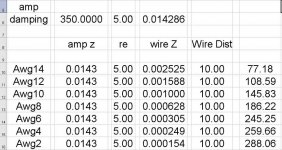
As long as you do not coil your speaker wires in a home application you will never have to worry about cable inductance or capacitance regardless of the wire you choose making enough of an effect on your sound that you will be able to measure or hear.... it is that negligable...
Well the skinny is, unless you are doing a 1000 foot run of wire you really will not need to worry about speaker wire capacitance even a little bit in a home app with a high damping amp... Maybe on the old tube amps and low damp amps but not the good amps today... a lot of hoopla about nothing...
If you are picking up a hafler here are the wire values for you
Madmike2 said:I am having a hard time justifying $$! for speaker wire when i am using a passive x-over. Why get good wire if it has to pass through that mess of caps and coils with silver solder and single thick strand leads. Does that not kill the benefits ?
I thought there was no coil on your bass driver? The series coil and the feed wires are the major components that add resistance to the circuit...
Series coils add considerable resistance like rcw said, between ,1 to 2 ohms... a series capacitor will add negligable resistance in the passband...
So if you have is a series cap on your tweet then you will maximize the returns on your wire... It is the series coils that are the culprit! no series coil then just get your wire resistance low and this will rock for you...
DonoMan said:Why get good capacitors and inductors if the signal will still be running through capacitors and inductors?
Besides, wire is CHEAP. Unless you're thinking of getting "interconnects", which I would agree with you on...
Well there are only 2 real reasons in the case for speakers to get one cap versus another...
one is stability over time and secondly the max tolerance value...
Film and poly caps have better stability over electolytic...
I go to the store take my meter match the electros and i am otta there...
Your room characteristics will do more to throw the cound off than a few percent difference in cap values
carlosfm said:
No.
Some tend to think of a speaker wire quality in terms of resistance, while it's not the most important thing.
You must think about the amp and not only the speakers.
The amp would like to see very low inductance and capacitance on it's outputs.
Everytime I go from a 2nd order to a 1st order crossover on a tweeter I hear improvements, harmonics of the instruments appear, natural decays, transparency, the breething of the singer.
Actually carlos speaker wire resistance is the most important thing unless you have a literally horrible amp... I assure you that as long as you do not coil up your speakers, in a home app, there is no wire I know that you can buy that has enough inductance or capacitance that you will either hear or measure!!
Of course when you go from a 2 pole to a single pole filter you wil hear more... if you have a 2 pole crossed over at 2k that means at 1k you are -12db and a single pole you are -6db so you should hear more...
now on my horns I cut the tweeter off with a 3 pole filter... Why? Because it matches the mechanical cutoff of the midrange horn... If I went to a 1 pole on that tweeter you would plug your ears and run! It all depends on the design...
well there is still a point... it is just diminished... I went from a number 14 to a number zero wire on my uncles infinite baffle speakers and it has a 6Mh coil on the woofer and everyone in the room noticed it... so its not like it is worthless, it just has dimished value as compared to a df of 200 for instance which above that point they claim no one can hear and improvement...Madmike2 said:But Carlos again i say There is no point if the passive is there 'period' the cable is broken up and the passive breaks the 'chain' . Its no longer one solid peice of BlahBlah$$ cable from amp lead to speaker lead. I am going off because i keep reading these reviews on cable and i want to get up and slap someone. Ya i got schooled changing from cheap RadioCrap Rca's to decent pro stuff, i heard that! But thats unbroken chain front to back with a nice chunky copper 1/4 inch jack to Copper jacketed RCA on copper wire. Speaker wire is nice silver/copper to -mess of wiring- to silver/copper to your amp and speakers. Impossible to tell me there is an improvement in sound. Electrically impossible.
Sigh. I gotta go and see if i can buy that Adcom now. I am so disappointed in reviewers. 50 year old guys saying they can hear 18k ....please. I am 39 and 15 k is a tickling in my ear. 🙁
Nothing can beat an active crossover... top shelf... nothing better... an active crossover goes before the amp adding nothing to interfere with the speaker circuit... on the other hand a passive crossover is the speaker circuit...carlosfm said:Mike, a good passive crossover is now worse than an active crossover.
Adding more active stages to the replay chain is also not good.
So, what I mean is: cable inductance and capacitance can have a marked effect on the sound.
As long as you do not coil your speaker wires in a home application you will never have to worry about cable inductance or capacitance regardless of the wire you choose making enough of an effect on your sound that you will be able to measure or hear.... it is that negligable...
Madmike2 said:Interesting. Well i can experiment to my hearts content but i am going in with a closed mind.
Back to experimenting 😡
Well the skinny is, unless you are doing a 1000 foot run of wire you really will not need to worry about speaker wire capacitance even a little bit in a home app with a high damping amp... Maybe on the old tube amps and low damp amps but not the good amps today... a lot of hoopla about nothing...
If you are picking up a hafler here are the wire values for you
Attachments
There is no coil in line with the woofer. Throughout this thread i was disassembling and experimenting and eventually the x-over became a capacitor only.
I am looking at a Hafler, as soon as i get an e-mail back telling where there is a dealer . The 9500 series? well i am not paying grand for that from a pawn shop. Not a chance in hell. A brand new p1500 is way under that price.
Also going to buy a 3.5uF Oil can capacitor. I dont like this 3 uF.
I am looking at a Hafler, as soon as i get an e-mail back telling where there is a dealer . The 9500 series? well i am not paying grand for that from a pawn shop. Not a chance in hell. A brand new p1500 is way under that price.
Also going to buy a 3.5uF Oil can capacitor. I dont like this 3 uF.
Re: Re: Re: Speaker wire ......... Why
Resistance is not the most important thing on speaker cables, we are talking usually small distances like 2~3m.
No speaker wire will have the same resistance for these kind of distances as a big series coil on a crossover.
You tend to think only in bass performance, while I look at the whole spectrum.
Of course, when you simplify a crossover you have to change things completely.
And you must select the drivers for that job, you can't just simplify on most speakers.
My point was: if you have coils and/or caps to ground on your crossover (steep slopes) the amp will NOT perform as well, because it doesn't like complex loads, inductance and capacitance must be minimized.
Speaker wire inductance and capacitance is another thing to add to the picture and spoil it.
I ask this to you as I asked to many:
If you have a properly designed speaker that doesn't need a crossover on the woofer and just has a series cap on the tweeter, would you go to active crossovers?
What for?
No, thanks.
You change a single series cap on the passive crossover for active filters full of junk op-amps?
Another active stage on the signal path?
The signal is too sensitive to play with, too easy to mess up.
Trying to solve an issue you get drawn into other issues.
More interconnects, plugs, contacts, active stages...
Get things simple and well done and you don't need active crossovers.
Active crossovers are a big step up in quality when you are using them on speakers that had (and needed) complex passive crossovers.
I love my Epos ES11 speakers.
rnrss said:Actually carlos speaker wire resistance is the most important thing unless you have a literally horrible amp... I assure you that as long as you do not coil up your speakers, in a home app, there is no wire I know that you can buy that has enough inductance or capacitance that you will either hear or measure!!
Of course when you go from a 2 pole to a single pole filter you wil hear more... if you have a 2 pole crossed over at 2k that means at 1k you are -12db and a single pole you are -6db so you should hear more...
now on my horns I cut the tweeter off with a 3 pole filter... Why? Because it matches the mechanical cutoff of the midrange horn... If I went to a 1 pole on that tweeter you would plug your ears and run! It all depends on the design...
Resistance is not the most important thing on speaker cables, we are talking usually small distances like 2~3m.
No speaker wire will have the same resistance for these kind of distances as a big series coil on a crossover.
You tend to think only in bass performance, while I look at the whole spectrum.
Of course, when you simplify a crossover you have to change things completely.
And you must select the drivers for that job, you can't just simplify on most speakers.
My point was: if you have coils and/or caps to ground on your crossover (steep slopes) the amp will NOT perform as well, because it doesn't like complex loads, inductance and capacitance must be minimized.
Speaker wire inductance and capacitance is another thing to add to the picture and spoil it.
rnrss said:Nothing can beat an active crossover... top shelf... nothing better... an active crossover goes before the amp adding nothing to interfere with the speaker circuit... on the other hand a passive crossover is the speaker circuit...
I ask this to you as I asked to many:
If you have a properly designed speaker that doesn't need a crossover on the woofer and just has a series cap on the tweeter, would you go to active crossovers?
What for?
No, thanks.
You change a single series cap on the passive crossover for active filters full of junk op-amps?
Another active stage on the signal path?
The signal is too sensitive to play with, too easy to mess up.
Trying to solve an issue you get drawn into other issues.
More interconnects, plugs, contacts, active stages...
Get things simple and well done and you don't need active crossovers.
Active crossovers are a big step up in quality when you are using them on speakers that had (and needed) complex passive crossovers.
I love my Epos ES11 speakers.
These speaker wire threads get real hot. Never fails.
I personally tried three different cable structures two of which consisted of the same basic able about 50 strands totalling a conductor diameter of 3mm. Each sounded different.
The first were just the cables twisted. The second using the same cable, but braiding it with a third clothes line so that it was possible to cross each other perpendicularly as mentioned in Speaker Builder (I think). The improvement was more depth in image and more life in the sound. I think the braided version had to use twice the length, but it's been a long time so I can only rememer it was longer. The third was a #14 guage Alpha Core foil cable. The improvment was better imaging and resolution.
These were all compared at least on a Hafler XL-280.
Inductors have the longest length of wire, so the difference is more significant even though DC resistance differ by about 0.2 Ohm only, the difference exceeds the effects adding a 1 ohm resistor in series.
soongsc said:These speaker wire threads get real hot. Never fails.
Blind tests threads too.
- Status
- Not open for further replies.
- Home
- Design & Build
- Parts
- Speaker wire ......... Why