the wiring in the pic below...
Fantastic looking build!! Congratulations!
😀 😀 😀
I'm now building the DC Speaker Protector Board and run out of C3 (47uf 50V). Could I use cap with bigger value like 100uf 50V?
That's fine but you'll be increasing the turn ON delay time.
Could I ask how to caculate this turn ON delay time base on value of C3?
Just a quick question before I order my boards:
Do I need two soft start and two speaker protection boards for a dual mono (2 trafo's) Honey Badger? Judging from the photo's I'd say I need one of both, but I'm not sure...
Thanks!
Do I need two soft start and two speaker protection boards for a dual mono (2 trafo's) Honey Badger? Judging from the photo's I'd say I need one of both, but I'm not sure...
Thanks!
If you can work out how to attach two relays, then you can isolate two speaker channels.
The two relays will either need double the voltage, or double the current.
Experimenting to find the correct component values to do this is potentially fatal since the circuit is direct to mains powered. This is normally banned from discussion on this Forum.
The two relays will either need double the voltage, or double the current.
Experimenting to find the correct component values to do this is potentially fatal since the circuit is direct to mains powered. This is normally banned from discussion on this Forum.
Andrew,
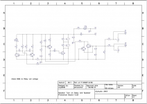
probably not. That's why I asked. Looking at the schematic, it looks like one protection board switches two loudspeakers. But, since I'm not sure, I thought I'd ask.
If I interpret your answer correctly, I need two speaker protection boards for two amplifier channels. Is that correct?
And: can I switch two PSU's with one soft start board? Or do I need one per PSU?
Attachments
Last edited:
Fantastic looking build!! Congratulations!
😀 😀 😀
Thanks, your top notch guide is what persuaded me to build one
Is there an article explaining how the boards work?
I believe this is it, the designers frequent this thread so any questions just ask...
One indicates the board is powered, the other the status of the relays. In my observation the LED flashes during startup before the relays latch, then it remains solidly lit to signify all is good and the relays have engaged.
Yes, the Green LED is simply telling you "there is power to the board".
I was able to use/fit small SMD LEDs in each spot.
Red.....Mouser# 630-HLMP-6300-F0011
Green.....Mouser# 630-HLMP-6500-F0011
Clarification:
The B.O.M. lists either 5v relays (x2) or 12v relays (x2).
The 12v option requires 24vAC input (from a transformer). I understand that.
But the 5v option recommends a 12vAC transformer connection.
Shouldn't that be a "10v" (if you are using two 5v relays) ??
My boards are working (4 second delay). I have two 5v relays, with a small 10v transformer @ 2.5VA. I believe that's as small as you can go (250mA).
A direct tap from a 10v transformer....is actually ~13vAC. My relays are getting 5.63vDC at their power inputs.
How much over-voltage can relays handle ?
.
Use a current saving resistor in the relay coil circuit.
If you also add a capacitor you can get a higher voltage kick into the coil and then a few tens of milliseconds later, as the cap becomes discharged, the current saver effect takes over and you can run the relay coils at <<5V, try 3.5Vdc or 4Vdc for cool running.
If you also add a capacitor you can get a higher voltage kick into the coil and then a few tens of milliseconds later, as the cap becomes discharged, the current saver effect takes over and you can run the relay coils at <<5V, try 3.5Vdc or 4Vdc for cool running.
Hello,
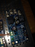
I have made this speaker protection board, reading carefully every post in this thread several times and double checking things on my board with those pics of others that have been posted here.
I connect up the primaries on the little transformer to the power on switch and the secondaries to the board. I have a 10A, 2x12v transformer and have the secondaries in series for 24v and am using 12v relays on the board, as per one of the early posts in this thread.
Everything is correctly installed on the board.
At power up, both LED's instantly light up. There is NO blinking LED for a few seconds and then steady light.
I do not have the speakers connected.
I am using this relay: G5LA-14 12DC - OMRON ELECTRONIC COMPONENTS - RELAY, SEALED, SPDT, 12VDC, 10A, THT | element14 Australia
OMRON G5LA-14 12DC for short.
Any ideas from anyone. Doesn't seem to work as is.
Hello,
I have made this speaker protection board, reading carefully every post in this thread several times and double checking things on my board with those pics of others that have been posted here.
I connect up the primaries on the little transformer to the power on switch and the secondaries to the board. I have a 10A, 2x12v transformer and have the secondaries in series for 24v and am using 12v relays on the board, as per one of the early posts in this thread.
Everything is correctly installed on the board.
At power up, both LED's instantly light up. There is NO blinking LED for a few seconds and then steady light.
I do not have the speakers connected.
I am using this relay: G5LA-14 12DC - OMRON ELECTRONIC COMPONENTS - RELAY, SEALED, SPDT, 12VDC, 10A, THT | element14 Australia
OMRON G5LA-14 12DC for short.
Any ideas from anyone. Doesn't seem to work as is.
Check everything. Start with the resistor values, capacitor values and polarity orientation, transistor lead orientation (this in particular can cause the description you mentioned).
Check everything. Start with the resistor values, capacitor values and polarity orientation, transistor lead orientation (this in particular can cause the description you mentioned).
I've already done all that, which is why I'm a bit lost.
One thing though, the power connection to the board is labelled +V and GND, indicating DC. If I'm connecting to transformer secondaries that is AC. It's confusing.
- Home
- The diyAudio Store
- Speaker Turn On Delay and DC Protector Board Set (V3)