The power connector PCB in the kit appears to come with a 2.0mm center pin, according to the Data Sheet for the PCB connector .
So...it appears the appropriate plug on the transformer needs the 2.1mm inner diameter orifice? I think my plug is the bigger 2.5mm and seems bigger on that inside diameter.
I really should just add this transformer to my next Digi-Key order. 421 in stock. Positive center correct? I trace the tracks and the center pin of PCB connector heads off to the amp power switch.
However, those two pads beside the PCB connector that are unlabeled on the silk, no jumper outline like the other jumpers, are a bit of a mystery. i wonder what they are for? AC pads for some optional device?
But dang...$13.06 for the wall wart could also acquire a couple of nice Nichicon KG Gold Tunes for my active crossover power supply.
Last edited:
40 watt & all,
MPJA, Inc.
Item #18249 PA, A !6.5 VAC wall wart...2.4 A...$6.95 + S&H
No need to worry about "enough" power. 😉 Get a power cord and put it all in one case...
MPJA, Inc.
Item #18249 PA, A !6.5 VAC wall wart...2.4 A...$6.95 + S&H
No need to worry about "enough" power. 😉 Get a power cord and put it all in one case...
A]: "...more power, Scotty!"
B]: "...she can't take much more of this, Captain!"
C]: "...Beam me up Scotty...there's no intelligent life here!"
40 watt & all,
MPJA, Inc.
Item #18249 PA, A !6.5 VAC wall wart...2.4 A...$6.95 + S&H
No need to worry about "enough" power. 😉 Get a power cord and put it all in one case...
Ooooooh!!! Light bulbs went off! So those two pads to the external side of the PCB connector could accept the pigtails from the nekked transformer output wires or a typical IEC socket and a computer type power cord with the transformer in the case. No shortage of those.
I need to rethink my case. I'm making one from scratch anyway and was about half-way through. Going for a matched appearance with my chip amp case might be nice. I was planning on veneering the jig case to match my chip amp so why not have other appearance features match, like size and rear connects.
16VAC X 1.40=22.4VDC post rectifier diodes.
The caps should be alright with that. We only need 1 watt though. I still wonder 840 milivolts 12VAC would produce the needed watt.
12VACX1.4=16.8VDC at 840mA would produce?...Oh dear..I better search the forums for the math formulas. The dreaded moment of audio math has dawned...😱
Don't tell me though! [because I should know at least this basic math for this hobby]
Snap-In panel mount led holder
Rat Shack # 276-079, black plastic, but much nicer than a loose led peaking its green head through a hole. peek-a-boo! 😀
The specifics: 5mm dia. led X 6.5mm (1/4") hole
I'm gonna use an 18 VAC transformer and DARE the caps to fail...
Rat Shack # 276-079, black plastic, but much nicer than a loose led peaking its green head through a hole. peek-a-boo! 😀
The specifics: 5mm dia. led X 6.5mm (1/4") hole
I do that to peopleOoooooh!!! Light bulbs went off!
I'm gonna use an 18 VAC transformer and DARE the caps to fail...
Last edited:
I'm gonna use an 18 VAC transformer and DARE the caps to fail...
Awww...you just want to have a test result where you can say: "See! My full range driver really IS 105db efficient!" 😀😀😀😛
what is the digikey part number for the (J5) mic input jack for the holes are smaller or do I just need to drill them out and use the same as the input and output part #
two holes for what
There are two holes parallel to the left of the AC inlet with no component info , so I am taking it to be a board jumper. Yet I want to be sure what goes there
There are two holes parallel to the left of the AC inlet with no component info , so I am taking it to be a board jumper. Yet I want to be sure what goes there
mcmahan48
The 2 unmarked holes adjacent to "J2" should not get a jumper. To do so would short the AC input. I can only speculate they could be used to provide AC to an off-board location.
The 2 unmarked holes adjacent to "J2" should not get a jumper. To do so would short the AC input. I can only speculate they could be used to provide AC to an off-board location.
...or do I just need to drill them out and use the same as the input and output part #
J3, J5 & J6 use the same part.
How do you test speakers with this jig?
Is there a "cookbook" that tells how to do this similar to the "manual" Zaph laid out for Sound Easy?
Is there a "cookbook" that tells how to do this similar to the "manual" Zaph laid out for Sound Easy?
Hi,
I will start up a thread on that subject once a few of these have been assembled.
🙂
Sorry to all for the long delay.
I will get back into the swing of things shortly and your continued patience is appreciated.
The jig is a modified version of the Wallin jig and the use of it is nearly identical. There is a ton of documentation on using Speaker Workshop with a jig like this. HERE is a good place to start.
I'll get the setup thread on track as soon as possible.
Any word on the user's manual thread? I just finished assembling the board and everything seems to be ok. Can't wait to start making impedance measurements.
Here are detailed instructions for assembly of the speaker testing jig designed HERE.
Please let me finish posting all of the instructions before you contribute or ask a question.
First, I know this is an old thread. It's also apparent the maker of this jig never created the user manual he promised. As I recently purchased an unassembled jig kit and it actually works I'll be happy to share what I learn and have learned as I go starting with getting it working.
If anybody still has one of these jigs and didn't get it to work the instructions left out two very important PARTS-SIDE jumpers that are marked on the board but not mentioned in the instructions. I fussed with the one I recently purchased and only noticed that in the pictures there are jumpers on the board where they are outlined in white but they aren't mentioned in the instructions. Once I installed the jumpers it seems to work fine.
Also of interest, I decided to use a full 24v PS and although it seems to work fine the resistor for the LED (R1) is only 1/8 watt and starts to get hot and stink after only a a minute or two. Thankfully the transformer I bought is a 24v secondary winding with a center tap so I can just switch to 12v and not have to replace the R1 resistor but it seems the only solution is to replace it with a 1/4 or 1/2 watt version. I haven't seen any other issues with the jig so far.
If anybody has one of these and is using it can you verify the IMP measurement procedure?
It seems the logical way to do this is with only 1 set of probes. It would seem obvious to get two dual banana connectors (red & black) and place one between both RED test lead plugs and the other between both black plugs. Then run the testing leads (12Gauge Monster wire?) down to the speaker for testing and clip them on. This should use the jig amp to excite the speaker and the IMP line-in to measure it. I was hoping I wouldn't need to purchase two sets of test leads. Monster wire is very expensive.
Monster wire
Siggma,
you don't have to use monster wire. You can go to your local electrical supply and pick up 2 different color 12 gauge stranded wire and twist them around each other for noise rejection.
-Matt
Siggma,
you don't have to use monster wire. You can go to your local electrical supply and pick up 2 different color 12 gauge stranded wire and twist them around each other for noise rejection.
-Matt
I have one assembled that I used a few times, I'd be willing to sell it for the original price. Meaning that I wasn't trying to sell it, but if somebody wanted one and they'd get more use out of it, then I guess I don't mind selling it. Mine is painted with Rustoleum "hammered" dark grey semi-metallic paint. If you're interested I could take a picture of it later this week.
I'm sad that MJL21193 hasn't come back. I wonder if he's OK? I think it's time that I try to use this little jig again soon.
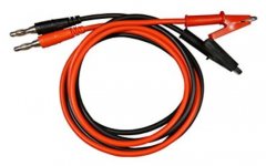
I might pickup some of these:
"Heavy Duty" 1m Banana Plug to "Mini Clip Test Leads
I might pickup some of these:
"Heavy Duty" 1m Banana Plug to "Mini Clip Test Leads
Attachments
- Status
- Not open for further replies.
- Home
- Design & Build
- Construction Tips
- Speaker Testing Jig Assembly Thread