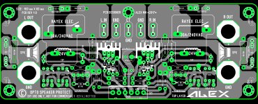

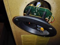
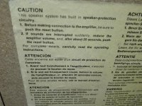
The back panel shows the typical reset button of a (thermal?/bimetallic?) circuit breaker, the PCB shows a conventional crossover network, no protection circuits or elements (fuses, thermistors, varistors) visible.
There is "something" between both which may solve the mystery.
There is "something" between both which may solve the mystery.
The back panel shows the typical reset button of a (thermal?/bimetallic?) circuit breaker, the PCB shows a conventional crossover network, no protection circuits or elements (fuses, thermistors, varistors) visible.
There is "something" between both which may solve the mystery.
JM
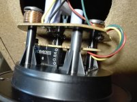
The photo corresponds to the same piece, photographed from the inside (by me) and from the outside (I found it on the web, it saved me the work).
The very simple (2-way) Xover and protection circuit are mounted on that PCB only.
The red button that resets the circuit penetrates inside one of the coils.
I have no idea what to call that piece.
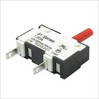
the standoffs create enough space for a thermal breaker between the terminal cup and the x-over. the ones used in the Technics speakers are smaller and cheaper i know i used to own a pair in the days gone by...
That piece seems to be, I will have to work 😀 to remove this doubt, thank you !
Mystery solved, turk 182 is right, and it is the same size as the photo. Good memory ! 😉
Thermal circuit breaker .... calculated to cut when a predetermined current passes through it, simple and effective.
Thermal circuit breaker .... calculated to cut when a predetermined current passes through it, simple and effective.
Attachments
Last edited:
You mean the OP, right
? 😀
I also hope that you decide once and for all not to use fuses ! 🙄
Merry Christmas to you too bro !
? 😀
I also hope that you decide once and for all not to use fuses ! 🙄
Merry Christmas to you too bro !
- Home
- Amplifiers
- Solid State
- Speaker protection with air coils and fuses