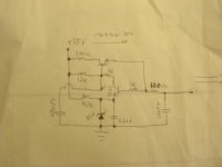
Will this work?
Considering the speaker expects 2 signals
1. the DC offset at the output when the amp is healthy and idling
2. an audio signal that is crossing zero.
By this I understand that 2 simple circuits should do the job
1. A low (safe) voltage detector
2.A zero crossing detection every 50mS or less.
One of the two should be happening, then the speaker is safe.
This method should protect the speakers in any case.
Am I correct. shooooot...
Gajanan Phadte
Hi,
that does not sound right.
Sampling at 50mS intervals might miss the event. Worse you could end up sampling in between a series of catastrophic events
Low DC offset is not a severe problem. High DC is a problem that can only be tolerated for a relatively short time.
that does not sound right.
Sampling at 50mS intervals might miss the event. Worse you could end up sampling in between a series of catastrophic events
Low DC offset is not a severe problem. High DC is a problem that can only be tolerated for a relatively short time.
AndrewT wrote
looks like I have not framed it in right words
sampling will not be done. Only zero crossing detection and the absence of this zero crossing will raise an alarm. Considering the lowest frequency to be 20Hz, if the crossong does not occur for more then say 60mS or more, then this raises an alarm and activates the protecion whatever it may be. The zero crossing will keep happening and varying depending on the audio content and will be much faster for 20KHz.
Coming to a tweeter protecion - If the lowest freq is 4KHz the alarm should be raised if the zero crossing does not occur within the desired time period. Raising alarm be done little later. In this way a tweeter protection can be actvated much faster.
The circuit will keep watch on every consecutive zero crossing in the audio content.
In case of no audio input
I should have written
...speaker expects 2 signals
1. the LOW DC offset at the output...
Gajanan Phadte
Sampling at 50mS intervals might miss the event. Worse you could end up sampling in between a series of catastrophic events
looks like I have not framed it in right words
sampling will not be done. Only zero crossing detection and the absence of this zero crossing will raise an alarm. Considering the lowest frequency to be 20Hz, if the crossong does not occur for more then say 60mS or more, then this raises an alarm and activates the protecion whatever it may be. The zero crossing will keep happening and varying depending on the audio content and will be much faster for 20KHz.
Coming to a tweeter protecion - If the lowest freq is 4KHz the alarm should be raised if the zero crossing does not occur within the desired time period. Raising alarm be done little later. In this way a tweeter protection can be actvated much faster.
The circuit will keep watch on every consecutive zero crossing in the audio content.
In case of no audio input
...speaker expects 2 signals
1. the DC offset at the output...
I should have written
...speaker expects 2 signals
1. the LOW DC offset at the output...
Gajanan Phadte
What happens when you have a quiet passage with effectively no signal??? won't the protection cut in?
Also what happens if the amp is clipping severely?? you will still have a zero crossing but your tweeters will most likely be toast 🙂
Tony.
Also what happens if the amp is clipping severely?? you will still have a zero crossing but your tweeters will most likely be toast 🙂
Tony.
Kind of thinking on the fly here, but couldn't you sense output collector current, reference this as a voltage and compare to output voltage? Set up comparison limits based below SOA limits, of course taking load reactance into account. This way if you have a speaker short, lots of current with little voltage would trigger the circuit, or if biasing fails and saturation occurs.
I will have to think of how this could be done....
I will have to think of how this could be done....
Hi CBS240,
That sounds like what some protection circuits do, except we look at derived emitter current. Emitter current = collector current + base current. The error isn't large so this is the current art.
-Chris
That sounds like what some protection circuits do, except we look at derived emitter current. Emitter current = collector current + base current. The error isn't large so this is the current art.
-Chris
Protecting the speaker is one thing, protecting the amp is another, and both may be needed. For protecting the speaker I think a zero-dector can work. Output must be zero (within a few mV) or pass zero frequently. Simple and nice!
Hi bjornagain,
I would place speaker protection as a #1 concern. Protecting the amp is best done by shutting off the power supply. Latching is the best.
Then the amp can be repaired and it is born again! 😉
-Chris
I would place speaker protection as a #1 concern. Protecting the amp is best done by shutting off the power supply. Latching is the best.
Then the amp can be repaired and it is born again! 😉
-Chris
Agree, and current sensing can be done at the power supply, which will protect the supply from a faulty amp. A fuse may be the simplest of things. A eletronic fuse can interact with the speaker protection.
Hi bjornagain,
Yes, and we are back to the way many manufacturers do it. Simple and effective.
-Chris
Yes, and we are back to the way many manufacturers do it. Simple and effective.
-Chris
I have made a circuit once before that used two PS. One +/-72V, regulated to +/- 60V. This only required small current to drive the front end and bias, and +/-55V for the output stage. The +/-60V regulators could be turned on or off with a +5V logic. When this happend, Vbe of drivers and outputs bias to 0V and outputs became "open circuits" No fuses or relays, all solid state...much faster. A fuse may not break fast enough to save the transistor.🙄 I'm sure there are many ways to do something similar.
Hi CBS240,
I like to regulate the voltage amp on it's own. Much better sonics. THe only thing is I like to leave the voltage amp running last on power off. That way the DC offset is stable until the relay (yes, the hated relay) opens. You could achieve a similar function by clamping the bias voltage with an optocoupler.
What do you think?
-Chris
Yes, since there is less sag on the "rail" supplying the front end and VAS, I find much less PS cmponents to affect the audio, even when using just filtered DC to power the outputs and drivers. Seems better to use like 5V larger rails and degeneration resistors so that satuation of VAS doesn't occur during rail to rail operation. I use a simple 2 transisor zener referenced feedback regulator in the last circuit I made, which seems to have much better load rejection than the straight up series, 1 trans. zener regulator. It does need some small caps to keep it from occilating though. Still simple but effective with smaller currents. This even with half wave rectification. Of course I drop like 10V across the reg. circuit. Plenty of ripple room.😎anatech said:Hi CBS240,
I like to regulate the voltage amp on it's own. Much better sonics.
THe only thing is I like to leave the voltage amp running last on power off. That way the DC offset is stable until the relay (yes, the hated relay) opens. You could achieve a similar function by clamping the bias voltage with an optocoupler.
What do you think?
-Chris
Nothing really against relays, they are tried and true protection methods. I think SS protection could be more reliable and not degrade with time and contact corrosion.
The circuit I used was a duel op-amp, as comparators, in parralell -in's connected to +in's. With a simple voltage divider, +5V switched the op-amps to turn on the regulators for both sides at the same time.(basically a feedback pair to switch on the voltage source for a zener reference) When the op-amps reverse bias the FB's, the regulator referencees to 0V. The big drawback is all the added complexity.(this is where you learn to love SMD's😉 ) The only noise made was a small 'tick' sound, that frankly wasn't a problem. DC offset didn't change from zero and I could switch the circuit on and off rapidly even when cranking audio. It seemed to work like a mute button. This all while direct coupled to speaker and power rails.(I know, I'm just asking for it here
 ) When the voltage source supplying the input stage, VAS, and the bias circuit for the outputs switches from +/-60V to 0V within uS's, the bases of the drivers/outputs are floating with the emitters referenced to ground. With no current source there is no conduction either way, effectivly clamping the bias. I think however, that this smooth operation was due to the circuit which seemed to be stable and had tolerance of the voltage for the front end. One of these days I will get back to it and maybe figure out how to include some type of sensing circuit for a logic control circuit.
I used this switch method in another circuit and the switching was not so smooth as it seemed to take longer to stabilize. I think this is a big factor whether or not this aproach would work. That circuit was crappy anyway and has been chalked up to another learning experience.😀
Hi Cbs,
could you post your lo I regulator schematic?
I am planning zener referenced 1 transistor for the Volt amp stage, but if your experience says otherwise I can change.
I will hold the ultra low noise opamp regulators for low level stages.
could you post your lo I regulator schematic?
I am planning zener referenced 1 transistor for the Volt amp stage, but if your experience says otherwise I can change.
I will hold the ultra low noise opamp regulators for low level stages.
Hello!
i construct and build two pice of my PCB v1.0
for the Project 33 - Loudspeaker Protection and Muting from Elliott Sound Products.
After some changes to PCB v1.01:
i'm happy with the results !
You can use the PCB free for diy only!
i construct and build two pice of my PCB v1.0
An externally hosted image should be here but it was not working when we last tested it.
for the Project 33 - Loudspeaker Protection and Muting from Elliott Sound Products.
After some changes to PCB v1.01:
An externally hosted image should be here but it was not working when we last tested it.
i'm happy with the results !
You can use the PCB free for diy only!
It seems to me you are forgetting something - time and frequency domain are connected. Amps also generally behave like a first order high pass, for a frequency on the order of a couple Hz.
All of this means that either you have to monitor the output of a low pass filter to be below a certain limit, or you can count zero crossings and generate a fault if they occur at a frequency below that of the said low pass filter turn-over. It's really two ways to do the same thing. This even includes the delay in DC detection you get from the filter version - it is the same delay you have to wait for the next zero crossing, and if it does not occur, generate a fault condition.
All of this means that either you have to monitor the output of a low pass filter to be below a certain limit, or you can count zero crossings and generate a fault if they occur at a frequency below that of the said low pass filter turn-over. It's really two ways to do the same thing. This even includes the delay in DC detection you get from the filter version - it is the same delay you have to wait for the next zero crossing, and if it does not occur, generate a fault condition.
Hi ilimzn,
Yes, I agree completely. Counting zero crossings needlessly complicates the protection circuit. Hmmmm, Yamaha might buy it from you come to think of it.
My experience in commercial products has shown that often complicated protection circuits are the thing that has failed. For this reason, a direct and effective protection scheme might be the best way to go. Your voltage amp regulator should also be reasonably simple and straight forward.
CBS240,
SMT's don't bother me unless higher voltages are involved, I just don't have a way to product PCBs. Still stuck at drilling holes, cleaning the board, connect the dots and etching.
-Chris
Hi Anatech,
When I was comparing 2 transistor to just 1, I noticed less voltage fluctuation with the 2 transistors. There was some RF occilation until I added the 470pf for stability and all was quiet.
As for SMD's, I just used cheap ready made general purose boards from Radio Shack of all places. The ones with square pads work well for bridging the traces, and the "daughter board" method works well for DIY....DIY IC's.😎
When I was comparing 2 transistor to just 1, I noticed less voltage fluctuation with the 2 transistors. There was some RF occilation until I added the 470pf for stability and all was quiet.
As for SMD's, I just used cheap ready made general purose boards from Radio Shack of all places.
The ones with square pads work well for bridging the traces, and the "daughter board" method works well for DIY....DIY IC's.😎Attachments
Hi CBS240,
I like that circuit with a little modification. I have not had oscillation problems yet. Drift is more a problem with the HV version.
I use a CCS to feed the pass transistor base, this improves noise rejection and load change behaviour for the better. My zener reference is fed from the pass transistor emitter.
I use this basic circuit for less than 50V supplies up to 350V supplies with component value changes. I need NTC resistors for the HV supplies to compensate for the zeners positive TC. Even tried zener strings, same problem.
Higher current, low voltage supplies get a darlington pair for the pass section.
-Chris
I use a CCS to feed the pass transistor base, this improves noise rejection and load change behaviour for the better. My zener reference is fed from the pass transistor emitter.
Ahh more added complexity. To me, complexity is not really a problem if the results are improved.😀 The CCS feed is noted. thanx
- Status
- Not open for further replies.
- Home
- Amplifiers
- Solid State
- Speaker Protection, new method?