Hi CBS240,
'Tis but an LED (red), two resistors and a transistor.
Experiment with one and let me know what you find. That's half the fun anyway.
-Chris
'Tis but an LED (red), two resistors and a transistor.
Experiment with one and let me know what you find. That's half the fun anyway.
-Chris
Hi anatech,
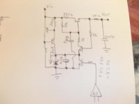
Unfortunatly I will not be home for another 2 weeks. I work on the road, currently in Rochester NY, nothing to do with electronics. Gotta make those donuts though...🙄 But while we are on the subject of regulators, what do you think of something like this?
Unfortunatly I will not be home for another 2 weeks. I work on the road, currently in Rochester NY, nothing to do with electronics.
Gotta make those donuts though...🙄 But while we are on the subject of regulators, what do you think of something like this?Attachments
Hi CBS240,
You're getting closer to me.
If you feed the zener from the output side of the pass element a resistor will supply a constant current. Use your CCS to feed the base of the pass element. The transistor normally used as an error amp is not set up to function that way. The shutdown feature will work fine.
-Chris
Hi Cbs,
that 100r resistor on the output of the reg.
@ 50mA it drops 5V. That ruins the regulator function.
Why have you put it there?
that 100r resistor on the output of the reg.
@ 50mA it drops 5V. That ruins the regulator function.
Why have you put it there?
Sorry Andrew T,
I discovered that circuit doesn't function and I deleted that post so as not to look like a total fool (you caught me before I deleted)
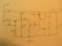
But, this seems like it would work better....or am I still the fool?
output 25.6V @like 10mA or so...sorry bad pic.
EDIT> you are right about the output resistor, should be scraped. Was thinking RF rejection, but I guess you could do that before the regulator? Should I put a resistor from anode of 5V zener to ground? (like 10K)
maybe it's time to stop and quit babbling😀
I discovered that circuit doesn't function and I deleted that post so as not to look like a total fool
(you caught me before I deleted)But, this seems like it would work better....or am I still the fool?
output 25.6V @like 10mA or so...sorry bad pic.
EDIT> you are right about the output resistor, should be scraped. Was thinking RF rejection, but I guess you could do that before the regulator? Should I put a resistor from anode of 5V zener to ground? (like 10K)
maybe it's time to stop
and quit babbling😀Attachments
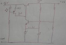
Hmm, so your just making a DC amplifier with gain. Seems simple enough, the voltage divider(gain) allows plenty of room for a resistor to supply constant current to the zener. I suppose it would still shut down by clamping the zener. I shall have to try a variation of this. Thanx anatech.
Hi CBS240,
Yup, short the zener and the output should drop like a stone. I haven't tried this, so let me know.
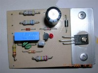
I haven't had any oscillation problems with this circuit at all. With a CCS driving the pass element, the performance is better than one would expect from this little circuit. I use red LED's for the CCS. A film cap is normally used across the zener, 0.22 to 1 uF should be fine. A capacitor is included on the input right on the board as well.
I've included a shot of the 280V version to give you an idea. The zener is hidden under a couple of thermisters to compensate for temperature shifts in the output voltage. It's a 100V zener.
-Chris
Yup, short the zener and the output should drop like a stone. I haven't tried this, so let me know.
I haven't had any oscillation problems with this circuit at all. With a CCS driving the pass element, the performance is better than one would expect from this little circuit. I use red LED's for the CCS. A film cap is normally used across the zener, 0.22 to 1 uF should be fine. A capacitor is included on the input right on the board as well.
I've included a shot of the 280V version to give you an idea. The zener is hidden under a couple of thermisters to compensate for temperature shifts in the output voltage. It's a 100V zener.
-Chris
Attachments
Bjorn wrote
Anatech wrote
UR correct, and I am protecting the speaker only. The amp can be fixed at a reasonably low cost, when it smokes.
Anatech wrote
Wintermute wrote
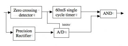
For quiet passge, the Low (safe) voltage detector will detect and prevent activation.
Yes. Clipping protection for tweeters has to be thought of.
Those blocks may look complicated especially the A/D but a VU ic like the LM3915 will do the function.
That is a quick functional block only to give u'all, the idea.
regards
Gajanan Phadte
Protecting the speaker is one thing, protecting the amp is another, and both may be needed. For protecting the speaker I think a zero-dector can work. Output must be zero (within a few mV) or pass zero frequently. Simple and nice!
Anatech wrote
I would place speaker protection as a #1 concern. Protecting the amp is best done by shutting off the power supply. Latching is the best.
Then the amp can be repaired and it is born again!
UR correct, and I am protecting the speaker only. The amp can be fixed at a reasonably low cost, when it smokes.
Anatech wrote
Below is a simple, hardware way of doing itHi ilimzn,
Yes, I agree completely. Counting zero crossings needlessly complicates the protection circuit.
Wintermute wrote
What happens when you have a quiet passage with effectively no signal??? won't the protection cut in?
Also what happens if the amp is clipping severely?? you will still have a zero crossing but your tweeters will most likely be toast
For quiet passge, the Low (safe) voltage detector will detect and prevent activation.
Yes. Clipping protection for tweeters has to be thought of.
Those blocks may look complicated especially the A/D but a VU ic like the LM3915 will do the function.
That is a quick functional block only to give u'all, the idea.
regards
Gajanan Phadte
Attachments
dr.strangelove3 said:Does a more convetional dc protection detect clipping?
I know the dc detection circuit in my amp doesn't (as I blew a lot of tweeters at parties in my uni days).... but thought I'd throw it in there since it is something that I've needed in the past. I guess a conventional clipping indicator could be added into the block diagram.....
Tony.
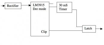
Looking at the clip indicators...
use of VU meter ic like LM3915 will detect clipping and protect tweeters.
Now that means I have to find some way of implementing all the protection necessities with minimum components
a quick on the fly thought, will it work?
regards
Gajanan Phadte
use of VU meter ic like LM3915 will detect clipping and protect tweeters.
Now that means I have to find some way of implementing all the protection necessities with minimum components
a quick on the fly thought, will it work?
regards
Gajanan Phadte
Attachments
To detect clipping. McIntosh stuck a diff pair across the inputs of the active diff pair in the amp. "power guard". When the amp clips, the added on diff pais saturates and gives you an indication. Pretty cool I think.
-Chris
-Chris
I am thinking of a protection circuit like this for a couple of months now.
The same "zero" volts detector can be used to detect clipping by measuring the output voltage vs power supply voltage.
Furthermore the same "zero" volt detector could be used to detect the amplifier goining from class A to class B.
All those nice detection lights on an amplifier....
I hope with that one I can convince my girlfiend we don't need all those damm christmas lights in the house. This one would do just as nice.
Self wrote
Oh! I missed the low (safe) voltage detector.
Gajanan Phadte
a quick on the fly thought, will it work?
Oh! I missed the low (safe) voltage detector.
Gajanan Phadte
anatech wrote
Hi chris,
Thanks for all the suggestions for modifying the amps for protection. To tell u frankly, while I was going through those 40 pages on one forum,this idea was conceived.
All the protection was thought of taking power amp as a black box.
regards
Gajanan Phadte
To detect clipping. McIntosh stuck a diff pair across the inputs of the active diff pair in the amp. "power guard". When the amp clips, the added on diff pais saturates and gives you an indication. Pretty cool I think.
Hi chris,
Thanks for all the suggestions for modifying the amps for protection. To tell u frankly, while I was going through those 40 pages on one forum,this idea was conceived.
All the protection was thought of taking power amp as a black box.
regards
Gajanan Phadte
Hi gmphadte,
Adcom monitors the diff pair and indicates clip in another way. Both work on the principle that the diff pair will saturate when it can not correct the audio signal. I just thought the McIntosh method was insightful. When you first see it on the schematic, you think "what the devil is that for?"
-Chris
- Status
- Not open for further replies.
- Home
- Amplifiers
- Solid State
- Speaker Protection, new method?