Hi!
I am trying to build a speaker protection circuit with relay, doing protection against DC offset, delay at powering, and AC loss detection.
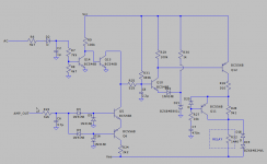
It is for a mono amplifier, with +/-20V power rails, and is based on Douglas Self circuit.
There are some things that I am not sure about. I am not familiar with switching circuits.
Q5/Q6 and Q13 discharge C8 throught R25 when power is removed for Q13, and if there is DC at the output for Q5/Q6. Could I connect them like this, or do I need one or two diodes to isolate them from each others? If yes, should I use pull-up resistors too?
I am not sure wich value choose for R25. It should limit the current, but as the discharge of C8 is really fast, I think I could use lower value as the transistors will dissipated power for a really short time.
I don’t really know how to choose the maximale value for R22 too. It limit the base current of the DC detector transistors, but as we don’t know wath he value of the offset will be, I don’t know how to calculate it.
For the loss of AC detector, Douglas Self said that C2 should be an electrolytic capacitor, but I don’t understand why, as in my simulation it work well with a 1uF capacitor. For now I have just use (only in simulator) random value with no calculation, it seem to work well but I have probably overlooked something.
There are probably things that could have be done better. Any critics would be really appreciated!
Thanks a lot for your help!
Please apologize my bad english.
I am trying to build a speaker protection circuit with relay, doing protection against DC offset, delay at powering, and AC loss detection.
It is for a mono amplifier, with +/-20V power rails, and is based on Douglas Self circuit.
There are some things that I am not sure about. I am not familiar with switching circuits.
Q5/Q6 and Q13 discharge C8 throught R25 when power is removed for Q13, and if there is DC at the output for Q5/Q6. Could I connect them like this, or do I need one or two diodes to isolate them from each others? If yes, should I use pull-up resistors too?
I am not sure wich value choose for R25. It should limit the current, but as the discharge of C8 is really fast, I think I could use lower value as the transistors will dissipated power for a really short time.
I don’t really know how to choose the maximale value for R22 too. It limit the base current of the DC detector transistors, but as we don’t know wath he value of the offset will be, I don’t know how to calculate it.
For the loss of AC detector, Douglas Self said that C2 should be an electrolytic capacitor, but I don’t understand why, as in my simulation it work well with a 1uF capacitor. For now I have just use (only in simulator) random value with no calculation, it seem to work well but I have probably overlooked something.
There are probably things that could have be done better. Any critics would be really appreciated!
Thanks a lot for your help!
Please apologize my bad english.
Attachments
I like to use the MID400 for AC loss detection. Optical isolation, and detection in one cycle. It is an old part that used to be made by GI and I think ON owns it now.
Thanks mikeAtx!
I'll have a look to MID400 datasheet. But I would like to use only "standart parts" if possible, I should have specified it, sorry.
I don't need the AC loss detector to be really fast. The amp produce a noise something between 0.5s and 1s after the power is removed.
I'll have a look to MID400 datasheet. But I would like to use only "standart parts" if possible, I should have specified it, sorry.
I don't need the AC loss detector to be really fast. The amp produce a noise something between 0.5s and 1s after the power is removed.
I use virtually the same circuit in my amp and it has been faultless.
R6 and D2 can be duplicated to also monitor the other side of the secondary winding rather than just monitoring one side.
100k and 10k were originally the values used for the resistors at the input, arranged slightly differently to yours with no 1uF cap needed. Your R25 would be 100 ohm and the other electrolytics 10uF.
Your Q13 should be a high beta type.
Essentially the same circuit with differences 🙂 Look it up, September 1996 in Electronics World magazine.
Thanks!
I would like to be able to make it work with relay first, as this is easier to understand for me than MOSFETs, and I have already enought difficulties with this circuit. But I totally keep this in mind for next projects!consider the use of mosfets instead of relays.
I know this circuit. 🙂 In July 1999, Douglas Self published an improved version of it. (It is in "Audio power amplifier design" too.) This is the one I'm using as reference.Essentially the same circuit with differences Look it up, September 1996 in Electronics World magazine.
There have perhaps been a few variations of that circuit 🙂 Just looking at the one in edition 6 of Doug's book (fig 24.32) and that is slightly different again. I'll have the July 1999 mag tucked away.
The circuit works great. Instant disconnect of the speakers on power off and a repeatable delay even after a short mains interruption.
The circuit works great. Instant disconnect of the speakers on power off and a repeatable delay even after a short mains interruption.
I have no doubt it is working great. 🙂 I just try to adapt it to better suit my lower rail voltages. It also allowed me to use a lower value for the timing capacitor, so I don't have to use an electrolytic one.
Furthermore, I really would like to learn how to calculate the values of components, and not just copy it as it is.
Have you use it for DC offset protection too?
Furthermore, I really would like to learn how to calculate the values of components, and not just copy it as it is.
Have you use it for DC offset protection too?
I did add DC offset protection. Its a long time ago but it was based on Dougs circuit.
If you look at the board here you can see it is a similar design (post #267)
Output Relays
Component values are not very critical. The relay driver and any series resistor has to be able to drive the chosen coil value.
Its very important to ensure that any base bias resistors are able to fully turn on the transistors if using lower supply voltages. So that is things like the 100k's
Same applies to the AC detect input and also the DC detect input. The R values have to be low enough to allow the transistors to conduct correctly at the appropriate input levels.
Its a wired AND gate, no need for diodes as both transistors (Q5, Q13) are pulling down toward ground (or slightly below ground). The emitters of Q5 and Q6 are constrained to be within +/-1.3V of ground by the 1N4148s. Note you can replace all 4 1N4148s with a small bridge rectifier as the topology is the same.Hi!
I am trying to build a speaker protection circuit with relay, doing protection against DC offset, delay at powering, and AC loss detection.
It is for a mono amplifier, with +/-20V power rails, and is based on Douglas Self circuit.
There are some things that I am not sure about. I am not familiar with switching circuits.
Q5/Q6 and Q13 discharge C8 throught R25 when power is removed for Q13, and if there is DC at the output for Q5/Q6. Could I connect them like this, or do I need one or two diodes to isolate them from each others? If yes, should I use pull-up resistors too?
Probably, the value isn't crucial, I'd make it 470 anyway as that's an E12 value.I am not sure wich value choose for R25. It should limit the current, but as the discharge of C8 is really fast, I think I could use lower value as the transistors will dissipated power for a really short time.
The pull up on C6 is 680k, meaning Q5/Q6/Q13 only need to pass 30µA to operate the protection, so their base currents are miniscule.I don’t really know how to choose the maximale value for R22 too. It limit the base current of the DC detector transistors, but as we don’t know wath he value of the offset will be, I don’t know how to calculate it.
R22 and C6 are chosen so that R22 can handle full swing voltages without burning out, and their time-constant is suitable to allow 20Hz full swing to
just fail to operate the protection. Make R22 too small and it would have to
be a power resistor, too large and you'd be worrying about base-drive but given
only a microamp or so is needed I think its OK.
To keep the size down?For the loss of AC detector, Douglas Self said that C2 should be an electrolytic capacitor, but I don’t understand why, as in my simulation it work well with a 1uF capacitor. For now I have just use (only in simulator) random value with no calculation, it seem to work well but I have probably overlooked something.
There are probably things that could have be done better. Any critics would be really appreciated!
Thanks a lot for your help!
Please apologize my bad english.
How much of the described Self circuit from edition 6 is the same as what is in my edition 5, page 464 and on?
In regards to filtering and low frequencies, a lot has been made about DC amps and extended LF response. Well, I believe strongly in limiting LF response to minimize woofer excursion below Fb. I run a 40 Hz second order to my mains now, 15 Hz to my sub. That gives considerable margin separating base notes from rail fault. That is in addition to the crossover.
Any suggestions on currently available relays which do not have the issues he discusses with the frame? 30 years ago, I would have use surplus T-Bar relays.
As we are talking Self, I built a 'Blameless". Found it dull and lifeless. Too clean? Am I used to the "warm", read a bit more low order even harmonics? Very educational though. Learned a lot form Self, Cordell, Pass, Diddon, and Curl when I built my MOSFET. Direct help from John.
On the subject of relays... I would never by choice go back to using mechanical relays these days. Solid state every time for me. Same applies to low level switching. It is always always always the mechanical contacts that fail and give trouble in any equipment as time passes.
Agree on the comments of the 'Blameless'. I built one using official boards and really wanted to like it. I even tried to convince myself it was the amp that was revealing and the fault must be in the source material. Sadly not, I found it just does not engage the listener although I persevered for several years with it.
Agree on the comments of the 'Blameless'. I built one using official boards and really wanted to like it. I even tried to convince myself it was the amp that was revealing and the fault must be in the source material. Sadly not, I found it just does not engage the listener although I persevered for several years with it.
For low level switching, some FET switches are OK, but I don't know if any device I would put in my speaker leads. Even using a FET to ground for output muting low level is shown to cause considerable distortion. As far as power goes, SSRs are a disaster as they cause DC offset. Found that out the hard way with buzzing transformers. I only use big relays for power now. One does need to pick the right relay contact.
Reminds me a few decades ago when were having issues with a power off safety switch in our tape drives. It had to accurately pass a few microvolts, but handle 90V @ 45A.
Reminds me a few decades ago when were having issues with a power off safety switch in our tape drives. It had to accurately pass a few microvolts, but handle 90V @ 45A.
Oh, for those following this thread who have not heard a "Blameless", go listen to first generation Cambridge amps. I understand they are better now.
Yes, relays can me a maintenance item, but so are electrolytics. A price we pay. 🙂
Yes, relays can me a maintenance item, but so are electrolytics. A price we pay. 🙂
Thanks! I will look more into this. Nice to see it is possible to drive ss relay with the same circuit too. I really want to try this later!I did add DC offset protection. Its a long time ago but it was based on Dougs circuit.
If you look at the board here you can see it is a similar design (post #267)
Output Relays
Thanks! In my simulation, when Q5 goes low, it was sinking current from Q13 collector. I found it strange, and that was what give me doubts. Furthermore, Douglas Self use a diode and a 220k pull up resistor on the DC detector side, but not on the AC loss detector side.Its a wired AND gate, no need for diodes as both transistors (Q5, Q13) are pulling down toward ground (or slightly below ground). The emitters of Q5 and Q6 are constrained to be within +/-1.3V of ground by the 1N4148s. Note you can replace all 4 1N4148s with a small bridge rectifier as the topology is the same.
This is what I would do too, 525 was just for simulation. But the original circuit use only 100ohm, hence my question.Probably, the value isn't crucial, I'd make it 470 anyway as that's an E12 value.
Nice, thanks a lot!The pull up on C6 is 680k, meaning Q5/Q6/Q13 only need to pass 30µA to operate the protection, so their base currents are miniscule.
R22 and C6 are chosen so that R22 can handle full swing voltages without burning out, and their time-constant is suitable to allow 20Hz full swing to
just fail to operate the protection. Make R22 too small and it would have to be a power resistor, too large and you'd be worrying about base-drive but given only a microamp or so is needed I think its OK.
Would it cause an issue to use ceramic capacitor here?To keep the size down?
Sorry, I don't know how the circuit in edition 5 is. You can find the one in edition 6 in Electronics World magazine from July 1999, or in "Self on Audio" too.How much of the described Self circuit from edition 6 is the same as what is in my edition 5, page 464 and on?
I will limit the bandwidth in the preamplier stage.In regards to filtering and low frequencies, a lot has been made about DC amps and extended LF response. Well, I believe strongly in limiting LF response to minimize woofer excursion below Fb. I run a 40 Hz second order to my mains now, 15 Hz to my sub. That gives considerable margin separating base notes from rail fault. That is in addition to the crossover.
Thanks a lot! I need some time to digest all those informations, but it really help! 🙂
For low level switching, some FET switches are OK, but I don't know if any device I would put in my speaker leads. Even using a FET to ground for output muting low level is shown to cause considerable distortion. As far as power goes, SSRs are a disaster as they cause DC offset. Found that out the hard way with buzzing transformers. I only use big relays for power now. One does need to pick the right relay contact.
Reminds me a few decades ago when were having issues with a power off safety switch in our tape drives. It had to accurately pass a few microvolts, but handle 90V @ 45A.
Modern power FET's have super on resistances, typically in the single milliohm region but the beauty of them is that its repeatable and constant over time unlike relays.
Small signal switching needs care, here I use JFET's in a series shunt arrangement in conjunction with a virtual earth stage such that the channel in use sees no signal voltage across either FET.
I agree on conventional SSR's for controlling large transformers. A triac can be used along with a FET relay (using power FET's) across the triac to short it out once any high surge current has passed.
This is the the thread that started it all, its a long running thread. Everything you need to know on FET relays should be in here:
Output Relays
Output Relays
- Home
- Amplifiers
- Solid State
- Speaker protection circuit questions