Nice Board Bonsai, you may be should consider this Mosfet, with higher voltage for 75V....I've designed a simple speaker protection board using the UPC1237 (Unisonic Taiwan is the manufacturer, originally uPC1237 from NEC) that uses mosfets rather than a relay to switch the speaker. The circuit operates from 25V to 75V with some resistor changes (detailed in the write-up), features power up/down muting, DC offset protection and an input to trip the protection on overcurrent (you will need to arrange your own short circuit detection - the board just takes an input for this as a trigger).
There's a presentation with the circuit, BOM and if you want a board, you can buy one off the website.
Hifisonix Speaker Protection Board
Happy soldering
🙂
MOSFET N-Ch 120V 179A
TK72E12N1,S1X(S
Last edited:

Nice Board Bonsai, you may be should consider this Mosfet, with higher voltage for 75V....
MOSFET N-Ch 120V 179A
TK72E12N1,S1X(S
That looks like an excellent mosfet - good prices as well!
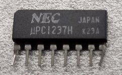
Here's a picture of the uPC1237 I got form St Quentin Radio in Paris.
Seems legit.
Jacques, looks good - you just have to try it!
I bought 5 of them from Ali express when I build a Slewmaster for very cheap, I have tested all of them, three of them worked 100%, the other two's delay to switch off on a fault was delayed. So if you buy a lot you can filter the bad ones out. But you want them working when needed. I don't think they work very hard, might be an option.🙂 and I have used Andrew's idea, work superbbbb.
Solid State DC protection
Hello Bonzai
greetings just want to ask you in the schematic posted where
on pcb will Amplifier output to protection go .This is for one ch
have to build same circuit for second ch will both 22k resistors
go to U6 input .
warm regards
Andrew
Hello Bonzai
greetings just want to ask you in the schematic posted where
on pcb will Amplifier output to protection go .This is for one ch
have to build same circuit for second ch will both 22k resistors
go to U6 input .
warm regards
Andrew
Attachments
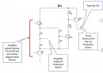
Andrew, for the current trip input, the ‘trip’ signals must be wire-OR’d.
The example circuits Inshowed do this. If any one of the two trip inputs pulls high, it will shut the output down.
The max current you can allow to flow into the trip pin is 3mA, so adjust the series resistors (I showed 22 k) for something below this. 1-2 mA will be fine.
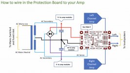
For overall hook-up, it’s per the diagram in the presentation here:-
The example circuits Inshowed do this. If any one of the two trip inputs pulls high, it will shut the output down.
The max current you can allow to flow into the trip pin is 3mA, so adjust the series resistors (I showed 22 k) for something below this. 1-2 mA will be fine.
For overall hook-up, it’s per the diagram in the presentation here:-
Attachments
Last edited:
other suitable optos
i searched farnells site, and it comes up with 30 optos for gate drivers
https://uk.farnell.com/w/c/optoelec...ase-style=dip&range=inc-in-stock&sort=P_PRICE
what specs should i look for to choose an opto for the ssr application?
i searched farnells site, and it comes up with 30 optos for gate drivers
https://uk.farnell.com/w/c/optoelec...ase-style=dip&range=inc-in-stock&sort=P_PRICE
what specs should i look for to choose an opto for the ssr application?

i searched farnells site, and it comes up with 30 optos for gate drivers
https://uk.farnell.com/w/c/optoelec...ase-style=dip&range=inc-in-stock&sort=P_PRICE
what specs should i look for to choose an opto for the ssr application?
ctrlx,
Unfortunately, those are optocouplers and not photovoltaic drivers.
With the optocoupler driver you would need to have an isolated power supply across the coupler Vcc and Vee pins. The output pin would then switch between these two pins. The advantage is that the switch extremely fast with peak output currents (some > 2A).
A photovoltaic drivers like the ones used in the Speaker Protection Board actually generate an output voltage that is derived from the internal LED - so you only have 2 output terminals. No additional supply needed. The disadvantage is that they switch slowly and especially so when loaded with the mosfet gate capacitance. But, it’s fast enough for our purposes in audio.
The only ones I’ve used are the VOM127 and the TLP191 (they are 1-1 pin compatible).
Andrew, what is the peak output current of your amp (ie fault current) and the value of your emitter degeneration resistors?
ooh sorry, i thought ctrix were asking for U1 in the Current Overload Detection Input schematic.
Bonsai Did you try ASSR-V621-002E , Dual channel photovoltaic Mosfet Driver?
Yesterday, I resisted the temptation to respond to ctrlx and Hicoco to point out that their suggestions were not photovoltaic couplers. But using typical optos to detect over current is a reasonable idea, instead of the discrete transistor circuit.
Another issue is the loss of power detection. The half wave rectifier circuit in the data sheet is a bit slow and may not be fast enough to de-thump the amp. Using full wave detection, you can reduce the response time to a bit more than the zero crossing, about 3mS, which is probably the most practical solution. But by phase shifting the AC, and or-ing two full wave detectors you can respond to loss of power in about 10uS. Probably over-kill for speaker protection but could be very useful for UPS. If anyone is interested, I can post some simulations.
Another issue is the loss of power detection. The half wave rectifier circuit in the data sheet is a bit slow and may not be fast enough to de-thump the amp. Using full wave detection, you can reduce the response time to a bit more than the zero crossing, about 3mS, which is probably the most practical solution. But by phase shifting the AC, and or-ing two full wave detectors you can respond to loss of power in about 10uS. Probably over-kill for speaker protection but could be very useful for UPS. If anyone is interested, I can post some simulations.
The UPC1237 works on the premises that the time constant of the PSU reservoir cap bank and amp load will be much longer than the divider+ filter cap time constant on the AC detect input.
On my commercial power amps, I use the mains signal zero crossings to reset a timer so the disable time is a shade over 8.33 ms (60 Hz) or 10 ms (50 Hz).
Almost all amp PSU’s will hold yo for 100’s of ms once the mains power is removed.
On my commercial power amps, I use the mains signal zero crossings to reset a timer so the disable time is a shade over 8.33 ms (60 Hz) or 10 ms (50 Hz).
Almost all amp PSU’s will hold yo for 100’s of ms once the mains power is removed.
- Home
- Amplifiers
- Solid State
- Speaker Protection Board