In my family, sons are very rare...
I am the last male of this branch ofthe family... also average life expactancy about 50 odd years going by the ones that passed away...
I am the last male of this branch ofthe family... also average life expactancy about 50 odd years going by the ones that passed away...
Your hand show 71 to 75
I think will be a good idea to you if i am rigth....because to go away so early and left your beautifull wife in earth...ahahahahah...man, you will be very damned watching things going on in earth!
Imagine the long strip of candidates to married her... the long strip in front of your house... everybody with flower in their hands to offer support and friendship to her.... grrrrrrrr!
Well...you are a very good man..maybe you will appreciate that..... not to left her alone...i can understand.... i would bust them..explode....detonate..boooom!
- "Woman is MINE!"
... i would say loud and clear..ready to send fire on them...
- "To hell to you all!"
.... i would say with my double barreled spitting fire from both mouthes... with salt and pepper cartridge directly into their hear bumpers!
Better to go with 73 years old.. she will be so destroyed by the time the same as you will be.....her face will have the moon cratera alike you have...this is fair..this is normal.
ahahahahhaa.
regards,
Carlos
Attachments


the uPC1237 is aslo manufactured by NTE as NTE7100 http://www.nteinc.com/specs/7100to7199/pdf/nte7100.pdf and is available from Mouser. This might be the route I take as well, but my circuit is a bridge and would need 2 of them per channel in parallel, becase both output offsets could be of equal value +/- VDC. Since the speaker doesn't connect to GND but rather floats between the two outputs, the chip would be fooled by the input resistors on pin 2.  Still cheaper and easier than the descrete alternitive, when considering PCB space.
Still cheaper and easier than the descrete alternitive, when considering PCB space.Pardon me, but, could we focus on the audio issues and find another forum for the family issues.
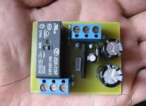
That said, is there an app note for this chip that can be read in English? Also, the board that is shown does not have any provisions for mounting.
I would be interested in a number of these boards if there is a way to operate from 80VDC. It would seem to me that a voltage divider or zener diode could solve the problem.
Tadiam, the one opened the thread did not felt bothered.
He is human and has a family.
Pardon to bother you with those awfull things... sorry..i was thinking you have family too.
I will unsubscribe related that thread..sorry for that Tadiam..we will talk direclty.
The guy is acid... i am going without return... will search sweet places with real educated folks.
By the way...Merry Christmas for you family Inlay.... they are not guilty.
Alcohol is a problem to drive..reduce focus.
regards,
Carlos
Re: Tadiam, the one opened the thread did not felt bothered.
Carlos,
Let's leave my family out of this. I find your rambling prose very difficult to read and understand. It is likely that English is not your native language and so you do the best you can. That's not intended to be an insult. It is what it is.
I'll start another thread on the output relay topic, specifically the NTE chip mentioned above, and go from there.
TO TEEMUK
If I can find an app note for the chip I'll design in the fault LED and loss of AC. It appears that there is a pin for loss of AC
destroyer X said:
He is human and has a family.
Pardon to bother you with those awfull things... sorry..i was thinking you have family too.
I will unsubscribe related that thread..sorry for that Tadiam..we will talk direclty.
The guy is acid... i am going without return... will search sweet places with real educated folks.
By the way...Merry Christmas for you family Inlay.... they are not guilty.
Alcohol is a problem to drive..reduce focus.
regards,
Carlos
Carlos,
Let's leave my family out of this. I find your rambling prose very difficult to read and understand. It is likely that English is not your native language and so you do the best you can. That's not intended to be an insult. It is what it is.
I'll start another thread on the output relay topic, specifically the NTE chip mentioned above, and go from there.
TO TEEMUK
If I can find an app note for the chip I'll design in the fault LED and loss of AC. It appears that there is a pin for loss of AC
Just the other day I was browsing through Randy Slone’s High Power Audio Amplifier Construction Manual when my eyes caught something interesting related to this thread: The chapter discussing speaker protection methods shows a discrete circuit that contains a clever way to realize the indicator LED: The relay driver transistor also triggers an astable multivibrator “flip-flop” circuit that controls the state of the indicator LED. As an addition, visual indication of errors is indicated with the vibrator’s oscillation speed: When LED is constantly on the circuit works correctly, flashing indicates that the DC protection is active. Speed of flashing indicates if the protection is activated due to DC fault (or startup delay) or due to thermal overload.
Unfortunately I can’t post schematics since they are copyrighted but if anyone happens to get their hands on the concerned book the circuit is worthwhile checking out.
d3imlay: Datasheet for uPC1237 can be found in English language (I belive from first hit with google) but unfortunately it is very simplified when compared to the Japanese version.

late Randy Slone's speaker protection circuit is not fast enough to open the relays during turn off.
How about this one... found it in one site which I don't remember where 😀
short description... note the unit is coonected in the speaker terminal. maybe somebody want to try in simulation.
The filter network comprises a pair of cascaded low pass filters R1 and R2 and capacitors C1 and C2. The high pass filter includes values for resistor R1 and R2 and capacitor C1 and C2 are selected so that DC and AC signals significantly below 20Hz in frequency, i.e. below 2Hz, are passed to the filter output line. The electrical values for R3 and C3 are selected so that signals significantly above 20,000 Hz, i.e. above 200,000 Hz are also passed to the output. As such, the filter blocks signals in normal audio band between 20Hz and 20,000 Hz while passing significantly outside the normal audio band to filter output.
Attachments
HiUPC1237HA(MS) Discontinued 04/1997
UPC1237HA Phase-out 04/2008
UPC1237C Limited production
http://www.necel.com/nesdis/image/IEP-730A.pdf
Look at page 4
Pin2 senses DC offset.
pin 3 is connected to ground or to ground via a cap to form a latching protection.
pin4 sences ac off through a diode and resistor
pin5 connects to ground
pin6 drives relay through a resistor, the other side of the relay connects to DC+ supply
pin7 connects to pin8 with external 56k resistor and has 33uf cap to ground
Two links bellow, does not active anymore. Anyone could upload them here??
http://www.necel.com/nesdis/image/IC-1806A.pdf
http://www.necel.com/nesdis/image/IEP-730A.pdf
- Status
- Not open for further replies.
- Home
- Amplifiers
- Solid State
- speaker protect schema here