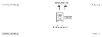
I have built up the circuit in the picture which the author of the circuit swears works.
I have copied the circuit onto a pcb and it doesn't work.
The mosfet gate circuit never charges up.
The 12 volt 100KHz square wave passes first capacitor ok but there is no charge passed to the other side of the diode.
The diodes are 1n4148 so are fast enough.
I built up a little test circuit on veroboard with a sig gen and that doesn't work either.
SPEAKER_PROTECTOR_SSR1 | harrabylad | Flickr
Did you return R4 to the same GND as the 100KHz input?The 12 volt 100KHz square wave passes first capacitor ok but there is no charge passed to the other side of the diode.
Isn't D3 reversed?
How about doing it the easy way?
View attachment 734519
I've been doing it this way for years, simple and reliable.
Mike
Thanks Mike that's a much better solution.
Did you return R4 to the same GND as the 100KHz input?
Isn't D3 reversed?
Yes R4 goes to same ground as 100KHz generator.
D3 is a Zener so right way around.
Modern switching mosfets are available with very low Rds(on) values of < 10m Ohms at reasonable Vds ratings of 100-200 volts. However, the gate charge for the most part is quite high and you have to supply enough current to charge this up quickly. Although the single opto is simpler, you have to make sure it switches the mosfet fast enough.
I am switching a 61 Amp load in about 80 microseconds (this is the total time from the application of the load to it being disconnected from the amplifier using 1 mosfet driver per channel. And that can be repeated that all day long without any degradation in the mosfet performance or risk of failure unlike an electro-mechanical relay.
I am switching a 61 Amp load in about 80 microseconds (this is the total time from the application of the load to it being disconnected from the amplifier using 1 mosfet driver per channel. And that can be repeated that all day long without any degradation in the mosfet performance or risk of failure unlike an electro-mechanical relay.
I am switching a 61 Amp load in about 80 microseconds (this is the total time from the application of the load to it being disconnected from the amplifier using 1 mosfet driver per channel. And that can be repeated that all day long without any degradation in the mosfet performance or risk of failure unlike an electro-mechanical relay.
which opto coupler are you using ?
This one here
https://www.mouser.co.uk/datasheet/2/427/vom1271t-244790.pdf
Vishay VOM1271.
however, there are quite a few others that will also work well. Dual channel types also available from some suppliers that you can wire in series or parallel for lower Rds(on) or faster switching.
https://www.mouser.co.uk/datasheet/2/427/vom1271t-244790.pdf
Vishay VOM1271.
however, there are quite a few others that will also work well. Dual channel types also available from some suppliers that you can wire in series or parallel for lower Rds(on) or faster switching.
Last edited:
This one here
https://www.mouser.co.uk/datasheet/2/427/vom1271t-244790.pdf
Vishay VOM1271.
however, there are quite a few others that will also work well. Dual channel types also available from some suppliers that you can wire in series or parallel for lower Rds(on) or faster switching.
Yeah, I usually parallel the outputs of two VOM1271s for faster switching times.
Mike
However, the gate charge for the most part is quite high and you have to supply enough current to charge this up quickly.
I am switching a 61 Amp load in about 80 microseconds (this is the total time from the application of the load to it being disconnected from the amplifier using 1 mosfet driver per channel.
Does it really matter if it switches in 80 us or 800, considering that a 25 millisecond long half sine pulse is perfectly valid and shouldn’t cause it to open?
How about doing it the easy way?
View attachment 734519
I've been doing it this way for years, simple and reliable.
Mike
So the mosfets dont even need a heatsink then, or a very tiny one.
Does it really matter if it switches in 80 us or 800, considering that a 25 millisecond long half sine pulse is perfectly valid and shouldn’t cause it to open?
Three a few things going on here - mosfet switching time and the time from fault detection to disengaging the speaker load.
1. You want to switch the mosfets quickly to minimise their power dissipation
2. If you do not use load line SOAR protection, but just current sensing, you want to switch off ASAP after detecting the overcurrent condition. This is the 80us figure I have on my system I mentioned earlier.
3. Separately, if you detect a DC offset or a catastrophic failure ( eg OPS fails short to one of the rails) you want to switch that quickly - 20 to 50 ms maximum. A speaker may handle that kind of DC power for a bit longer but you risk damage to it.
No heat sink needed. They are either ON so the resistance across them is a few milli-Ohms so they dissipate very little power or they are OFF and conduct no current.
A good idea to use upc1237 with mosfets then
- Status
- This old topic is closed. If you want to reopen this topic, contact a moderator using the "Report Post" button.
- Home
- Amplifiers
- Solid State
- Speaker protect circuit using mosfets

