I have been restoring an Akai AS-980 quadraphonic receiver - a big beast of a thing from about 1974. It had a blown fuse but replacing it didn't blow it again. I've replaced all the dial and indicator bulbs with led, cleaned all the controls and tried it with headphones. It sounded wonderful! As a last check before trying it with speakers I checked the dc at the speaker terminals. In stereo mode it was fine on both channels, just 2mV. I then switched to 4 channel (it does 50 watts/channel on stereo and 32 on each of the 4 channels) and it now had 750mV on all 4 channels - oh no! Back onto stereo and it showed again 2mV on L and R but 750 on the 2 rear channels. That seemed a bit strange to me so I wondered if anyone has any ideas on what to check? I have circuit diagrams and parts lists in the service manual.
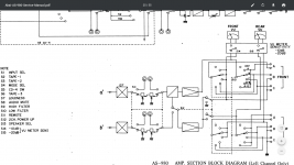
The arrangement is that there are 2 identical main amplifier boards, one does front R and back R and the other front L and back L.
I'll just confirm that with headphones it works just fine on all 4 channels.
I would much appreciate someone pointing me in the right direction.
The arrangement is that there are 2 identical main amplifier boards, one does front R and back R and the other front L and back L.
I'll just confirm that with headphones it works just fine on all 4 channels.
I would much appreciate someone pointing me in the right direction.
> 750mV
Put a 10 ohms (<100r) resistor on every output and try again.
There is a NFB resistor coming from a 0.7V Emitter through 5k to the output. If the output is NO-load, you read most of the 0.7V. With 8r load it calculates as 0.001V. (Cap leakage and settling will typically give a little more.)
Put a 10 ohms (<100r) resistor on every output and try again.
There is a NFB resistor coming from a 0.7V Emitter through 5k to the output. If the output is NO-load, you read most of the 0.7V. With 8r load it calculates as 0.001V. (Cap leakage and settling will typically give a little more.)
Attachments
not sure....
I guess there is something wrong somewhere that probably caused the fuse to blow in the first place. I'm attempting to attach a circuit diagram of the amp board so hope that works.
The output to the speakers is shown at points 8 and 11. As you see, the 62.3 input voltage comes from the fuses, one of which was blown. It may have blown by someone shorting out the speaker terminals or by something on the board - hard to tell.
Attachments
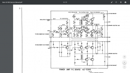
I can see that path from the emitter at .7v - I couldn't work out what that bit of the amp actually did. It goes through R20 to the output so could it be that resistor is faulty? Thanks for the help so far.
As PRR stated, you can measure the emmitervoltage (top R7) at the output when no load is connected. To reduce this (harmless) dc, you can add a bleeder (over the speaker terminals) of 120 ohm (sufficient W)) reducing this dc to some 16mV.
It is inherent to this topology.
It is inherent to this topology.
Without a load the time-constant to discharge the output blocking capacitor is 44 seconds. So after 5 minutes or so it ought to be reading OK.
The feedback point is a combination of before and after the blocking capacitor C8, so any charge on the capacitor will throw the output offset. (Its done this way to reduce capacitor distortion).
Because there is a blocking capacitor the output offset will invariably be tiny in real world use with a load. (Unless the cap leaks badly and the amp has a huge offset internally).
The dc offset doesn't reduce in time. I will try the solutions suggested but meanwhile I've been trying to understand the logic of the circuit and I think I now understand that at least. From the attached diagram you can note switch 12 which selects 4 channel or stereo boost. It is shown in the stereo boost position and here it takes the inverted signal to one of the amps and feeds it to the negative speaker terminals so this explains why in this mode I measure no dc offset on front L and R - it is on both + and - speaker terminals so the difference is zero. With switch 12 in the other position the 4 amp outputs separately drive the +ve speaker terminal with the other being grounded, so the dc appears on all 4 speakers. I will try measuring dc offset on each speaker terminal to ground just to confirm this.
I tried connecting a pair of old speakers to the FL and FR and in stereo mode they work just fine but switching to 4 channel there is a significant thump every time and again when switching back to stereo boost. Something is clearly wrong - they can't have been designed to do that. Maybe connecting the resistors will ameliorate this.
I checked all the 8 power transistors and they seem ok. I also checked R20 and that is ok too. I will check the various voltage levels against the circuit diagram later.
Thanks for the advice so far, guys.
Attachments
- Home
- Amplifiers
- Solid State
- Speaker dc offset in Akai AS-980