There is probably enough wire sticking out where it’s broken off to get a probe on it to do measurements. The value probably should be cleared up, if you’re contemplating dropping a 3.9 mH store bought inductor on there. If it is part of a low pass filter it can’t be anything else, but for a more advanced topology it could be 40. One significant figure of accuracy is all that is needed, really, if it’s an either-or. Put it in series with a raw speaker driver or 8 ohm resistor, and see where the cutoff is. If it’s 4 mH, it will sound like a typical woofer. If its 40 it will only send sub-bass frequency to it. Really muffled. You do not need good permanent connections, just a warm fuzzy before buying.
I understand that the broken wire looks to not be accessible, but I would be tempted to carefully peel away the plastic core that its wound on, just to see if you could get a bite on it and expose enough to solder to. It certainly couldn't be more trouble than winding a new coil yourself!
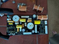
This might well be the answer, now that I have the board out and looking it over. The broken wire is longer than I thought and looks like enough to put some solder on it.
If my solder touches any of the other copper wire in the coil, will that be problematic?
I'll buy that meter Nixie recommended. I'm trying to get a hobby going here... 🙂

But with the cheapest Chinese crossover, unfortunately, like 90% of speakers today. You should take it all out and make a crossover with with better quality parts. Of course it is a big and expensive operatio
Honestly, half itching to do just that. Still, Sandy Gross' minions put out a nice sound on this one
There is nothing wrong with making your own crossover when the parts are available and not out of reach cost wise. In the meantime, go ahead and repair the broken wire from the inductor. You may not be aware that this wire is enameled, so adding solder can be done after removing any of this coating if it is there. Getting solder not to touch the existing enameled wire is also important. With care you can accomplish it. If there is enough wire available, you can shape it like a small letter j and then attach the repair wire with the same shape so as to help insure a good mechanical bond.
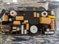
One thing that I would mention is that fact that the zip tie and glue failed to begin with. Now, this is just me talking here, but using an insulating material and a small stainless steel zip tie, will solve the breakage problem. Most any plastic zip tie is crap to begin with. I expect that you understand that care must be taken in the case of the metal zip tie. Maybe a good hot melt glue would be best to keep things from rattling. Notice that in one of your photos, the glue used hardly had any contact between the board and inductor. Not surprising, but you can do a better job than that and this will be a done deal.
One thing that I would mention is that fact that the zip tie and glue failed to begin with. Now, this is just me talking here, but using an insulating material and a small stainless steel zip tie, will solve the breakage problem. Most any plastic zip tie is crap to begin with. I expect that you understand that care must be taken in the case of the metal zip tie. Maybe a good hot melt glue would be best to keep things from rattling. Notice that in one of your photos, the glue used hardly had any contact between the board and inductor. Not surprising, but you can do a better job than that and this will be a done deal.
OK... now I really ruined the inductor. I pulled away some plastic, tugged at the bit of remaining wire and I broke it off. This probably means I can't get an induction measurement too? I'll have another one soon, and my brother has two, so I'll try to get this inductance question measured. I also have a line to a Def Tech tech support guy I'll ask....
To repair this, I seem to be left with rewinding the coil (until I get the inductance)?
Or maybe this is my total rebuild project (this speaker is for a stereo setup I'm building, and not in my theater, so timbre-match won't matter).
I was going to be disappointed if it was easy....
To repair this, I seem to be left with rewinding the coil (until I get the inductance)?
Or maybe this is my total rebuild project (this speaker is for a stereo setup I'm building, and not in my theater, so timbre-match won't matter).
I was going to be disappointed if it was easy....
Anyone who winds transformers can do that for you. He has a winder, counts the windings and winds identically.
Losing some turns shouldn't prevent you from measuring it. You can always put a few turns back on.
The problematic wire is broken from the bottom, and not visible. Could take more plastic off, but don't think I can unwind any from that end, nor get a touch on an independent part. Although, I'll try!
- Home
- Design & Build
- Parts
- Speaker crossover inductor replacement question