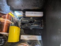
I'm having trouble figuring out a replacement for a broken inductor for my Definitive Technology Demand D15 tower. It appears to be 20awg solid core, but the inductance on the crossover board says 40mH. Is that right? Thoughts on an adequate replacement?
Also, my local hardware store went out of business and I bought 150' of 18awg wire for 70c. Can I double the wire to get 12awg? Is that "bi-wiring"?
Thank you for the help!
Also, my local hardware store went out of business and I bought 150' of 18awg wire for 70c. Can I double the wire to get 12awg? Is that "bi-wiring"?
Thank you for the help!
Attachments

How is the inductor broken, did the wire break? Just unwind about a foot and solder ind glue that inductor back on the board. You don't need a new one.
40mH is possible, but 4.0mH is more common.
No, and it's not a bifilar winding. More of a litz thing.Is that "bi-wiring"?
40mH is a huge inductor, I doubt this one is bigger than 1mH. And yes, it can be fixed, unscrew one thread and put it back on that PCB. They really are the worst possible.
It must be 4.0 mH, not 40 mH. Forget about winding yourself, buy 4 mH (or 3.9 mH) inductor.
But first: are you sure it is broken? What is the resistance (in Ohms)? Be sure to measure at the tinned edges of the wire - the rest of the wire is insulated by lacquer.
But first: are you sure it is broken? What is the resistance (in Ohms)? Be sure to measure at the tinned edges of the wire - the rest of the wire is insulated by lacquer.
Chances are the wire that’s broken off is the one that the end is buried at the bottom of the coil. Unless you can get a piece of it and unwind one turn from the inside, it’s pretty well screwed. One can always add a turn or two to the other end. Is it iron core? If it is, the value is really only sensitive to the number of turns (squared), and NOT the position on the coil former. Inductance meter is a valuable thing - and cheap-ish DMMs with that function are around. Woofer Tester can also be used. If it’s air core and you alter it in any way, it needs re-measurement and possible trimming. Air core would be 0.4 mH, not 4.0 in that small form factor. Either is possible with that typo on the board.
If you have magnet wire, rewind it if you can’t easily get to the broken off end. It’s not so many turns that you absolutely HAVE to have any sort of winding jig. Just keep the turns straight by hand. If it gets a little messier than the factory wind job, just add a few more turns. If you are into building or re-building inductors you NEED measurement capability of some sort. Doesn’t need .01% calibrated tolerance, if an off the shelf 3.9 mH inductor will do. If you don’t have magnet wire on hand that’s what I would do. Small rolls are stupidly priced - more than the damn choke - and a full 10 pound roll is $150-200. Salvaged wire off old transformers is FREE. Experts will tell you never to re-use magnet wire from transformers. It might not handle full line voltage anymore, but it will work HERE.
If you have magnet wire, rewind it if you can’t easily get to the broken off end. It’s not so many turns that you absolutely HAVE to have any sort of winding jig. Just keep the turns straight by hand. If it gets a little messier than the factory wind job, just add a few more turns. If you are into building or re-building inductors you NEED measurement capability of some sort. Doesn’t need .01% calibrated tolerance, if an off the shelf 3.9 mH inductor will do. If you don’t have magnet wire on hand that’s what I would do. Small rolls are stupidly priced - more than the damn choke - and a full 10 pound roll is $150-200. Salvaged wire off old transformers is FREE. Experts will tell you never to re-use magnet wire from transformers. It might not handle full line voltage anymore, but it will work HERE.
Hi, 40mH seams really high and unusual, although I don't know the design of this crossover.I'm having trouble figuring out a replacement for a broken inductor for my Definitive Technology Demand D15 tower. It appears to be 20awg solid core, but the inductance on the crossover board says 40mH. Is that right? Thoughts on an adequate replacement?
Anyways, I would rewind this inductor with a new wire of the same length/gauge (or even reuse the same wire - you can check if it still ok).
It will not be as beautiful as the original, but it will have similar inductance.
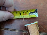
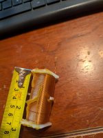
With a long screw, nuts and washers you can fixate the coil in a electric screwdriver - you need one with variable speed to keep speed very low.
This is what I use to wind inductors:
Regarding the use of a smaller AWG to make a bigger AWG, it works fine as long as you achieve the same cross section area in mm^2.Also, my local hardware store went out of business and I bought 150' of 18awg wire for 70c. Can I double the wire to get 12awg? Is that "bi-wiring"?
What matters is the total area of the conductors in parallel.
12AWG has an area of 3.31mm^2.
18AWG has an area of 0.823mm^2.
So, in order to achieve the same area of 12AWG, you need 4 x 18AWG in parallel (3.31/0.823 = 4).
In this case, it's not just doubling, but quadrupling.
That seems to be the case. How did it happen in general when everything was clamped and glued?Chances are the wire that’s broken off is the one that the end is buried at the bottom of the coil.
Its clearly printed as 40mH and it probably has 1000 turns or so (inductance goes with turns squared). It'll be 40mH.It must be 4.0 mH, not 40 mH. Forget about winding yourself, buy 4 mH (or 3.9 mH) inductor.
But first: are you sure it is broken? What is the resistance (in Ohms)? Be sure to measure at the tinned edges of the wire - the rest of the wire is insulated by lacquer.
40 mH is way outside of the range that filtering will require at 4-8 ohms unless it’s either a subwoofer crossed around 50 Hz, or in a conjugate network to eliminate the impedance peak. Way too thin a wire and way too small an (iron) core to be woofer/subwoofer crossover - unless you want saturation at 10 watts. If it is in a conjugate network, current isn’t high and DCR isn’t critical. It is, but there will be a resistor that can/should be adjusted if DCR changes. Also, will be in series with an R and a C, with the works in shunt with the woofer or midrange.
Getting a new choke in the 40 mH range, anywhere near that form factor will be impossible. Still LOOKS more like 4 mH to me. I suppose you’ll have to examine the circuit or measure the other one (without ruining it too).
Getting a new choke in the 40 mH range, anywhere near that form factor will be impossible. Still LOOKS more like 4 mH to me. I suppose you’ll have to examine the circuit or measure the other one (without ruining it too).
Typographical errors are not unheard off, but

The only sure way to determine the correct inductance is to measure the same "40 mH" inductor from the other loudspeaker crossover.
Typographical errors are not unheard off, but maybe you are right - with such thin wire and inductor dimensions, it may be 40 mH. So high inductance can be used only in some RLC notch filter or other compensation, but measured impedance of Definitive Technology Demand D15 has no indication of such use:Its clearly printed as 40mH and it probably has 1000 turns or so (inductance goes with turns squared). It'll be 40mH.
The only sure way to determine the correct inductance is to measure the same "40 mH" inductor from the other loudspeaker crossover.
That seems to be the case. How did it happen in general when everything was clamped and glued?
Yes, it's the one from the bottom, and I can barely even see the end. You can see the wire broken off still on the board in the first picture. Half inch or so. The other side came off at the solder weld and still has silver tips. Unfortunately, I don't have a second D15 yet. I have two of the larger D17s, but this is a slightly different crossover. I'll pull the crossover tonight and show you pics of each. Not sure if that will help.Chances are the wire that’s broken off is the one that the end is buried at the bottom of the coil.
The Demand series towers have a 2.7 mH metal core inductor that tends to break off and bang around, dislodging other components. On top of all that glue that doesn't work, there is a ziptie holding them down that seems to break at the glue point (reacting to the glue?). Solid, heavy, cleverly designed speakers, otherwise... 🙂
Last edited:
Is this when I buy a multimeter or other? An inductance meter? 🙂Can you measure the other D15 to confirm the inductance (if you have a pair)?
Thanks you all for all the help!!!
I understand that the broken wire looks to not be accessible, but I would be tempted to carefully peel away the plastic core that its wound on, just to see if you could get a bite on it and expose enough to solder to. It certainly couldn't be more trouble than winding a new coil yourself!
I rewound an old fan motor once and though I knew that it would be more work than it appeared, it was really a two person job for my set up.
Lastly and probably most important, was the new wire that you purchased an enameled wire that would be the proper wire to be used for a coil?
I rewound an old fan motor once and though I knew that it would be more work than it appeared, it was really a two person job for my set up.
Lastly and probably most important, was the new wire that you purchased an enameled wire that would be the proper wire to be used for a coil?
If you can’t unwind a full turn, it’s unlikely a solder joint will stay. It might be possible to pull the iron core out, then scrape away enough of the plastic bobbin from the inside. Enough to get a pair of needle nose on the wire, and unwind a turn. Then put the core back. A little epoxy to patch things, add a turn of insulated flexible wire, and you’re back in business.
But with the cheapest Chinese crossover, unfortunately, like 90% of speakers today. You should take it all out and make a crossover with with better quality parts. Of course it is a big and expensive operation.Solid, heavy, cleverly designed speakers, otherwise... 🙂
This measures inductances and capacities with sufficient precision. It's not accurate only at very small values (below 1nF and 0.1mH), but that doesn't matter in this case. I use this T7. If you could measure the value of that inductance, you would easily find a replacement on Aliexpress.
https://www.ebay.com/itm/316959765728
https://www.ebay.com/itm/316959765728
A cheap component tester like the one in post 19 is worth it, but otherwise I wouldn't get a decent LCR meter unless you have spare money lying around to waste.
If it were me I would do one of the following:
A: Buy a new inductor. With the silk screen it can't be much other than 4mH https://www.parts-express.com/Dayto...minated-Iron-Core-Inductor-257-662?quantity=1 (compare measurements and make sure it will fit.)
B: unwind the existing one and wind a new one with the same number of turns with the same diameter wire.
C: cut off the plastic on the side where the wire is broken and try to access the broken wire, like what Lxnay is suggesting.
- Home
- Design & Build
- Parts
- Speaker crossover inductor replacement question