Agree - corrected the title, added the link to the right measurements to the post #1.
Still this is always useful knowledge, it is very easy to put these errors inside your builds via an oversight. I have done it more than once even inside an IC.
Your Test Setup
Valery,
The RTX6001 and Dr Jordan's software look like an outstanding combination and quite affordable when compared to either a DScope III or AP test set.
Valery,
The RTX6001 and Dr Jordan's software look like an outstanding combination and quite affordable when compared to either a DScope III or AP test set.
Valery,
The RTX6001 and Dr Jordan's software look like an outstanding combination and quite affordable when compared to either a DScope III or AP test set.
Hi Carl,
Exactly, the great device - exceeded my expectations - and very good software.
I'm very happy with this combination - strongly recommend for FFT analysis.
Cheers,
Valery
BTW - yes, I have already tried to play the music through its DAC - it's really transparent, low noise - top performer 🙂
I have the CAYIN N3 which has the same AK4490EN DAC chip and use that as my output DAC for measurements - so I sort of have half of the RTX6001 🙂 Plus it is battery powered which makes for low noise and eliminates ground loops on the input side when I set it to play a precision 1kHz test tone FLAC file.
This RTX6001 looks very interesting. I am familiar with oscilloscope technology but I understand that nowdays a USB equipment is a very interesting alternative.
How would you compare the input analyser section with a quality oscilloscope ?
Input sensibility, time resolution wise, bandwidth.
What about synchronisation capability. I consider this as extremely important, so important that scopes that are poor on this are just junk to me. Do you have triggering on AC or DC with fine level adjust and capable of stable triggering on noisy signals. Do you get steady displays and capability to focus on details. May be this is dependant of the software, how is this done with RTX6001 ?
The RTX6001 is a distortion analyzer. It can be used as a scope in a pinch with appropriate software but wouldn't really replace one.
And vice versa a scope cannot replace a 24bit audio interface in terms of resolution of tiny voltages like noise or distortion.
Right, audio analyzer, like RTX6001, does not replace the scope. I've got a couple of good digital scopes, one of them is always connected to the amplifier's output even when I measure the spectrums, THD, IMD, step response, etc. with the analyzer.
The same thing about the software - WinAudioMLS by Dr.Jordan is excellent for FFT analysis and accurate measurements, but very inconvenient as a scope (possible, but inconvenient).
Technically, even the ADC sections are built to satisfy different requirements:
- Audio analyzer - high accuracy (24/32 bit) at a relatively low sample rate (up to 200KHz);
- Oscilloscope - much lower accuracy, but much higher sample rate (1-2GHz and above).
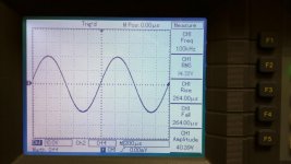
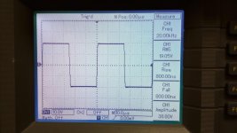
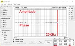
USB scopes are a separate "class" of instruments - I own one, mostly used for automatic bode plot building - a cool function - however, for everyday use, nothing is handier than a "classic" scope with all the physical knobs, buttons and quick measurement functionality of the modern scopes.
First 2 pictures - a physical scope with quick measurements, the 3-rd picture - Velleman USB scope's auto bode plot (red marks are added manually).
The same thing about the software - WinAudioMLS by Dr.Jordan is excellent for FFT analysis and accurate measurements, but very inconvenient as a scope (possible, but inconvenient).
Technically, even the ADC sections are built to satisfy different requirements:
- Audio analyzer - high accuracy (24/32 bit) at a relatively low sample rate (up to 200KHz);
- Oscilloscope - much lower accuracy, but much higher sample rate (1-2GHz and above).
USB scopes are a separate "class" of instruments - I own one, mostly used for automatic bode plot building - a cool function - however, for everyday use, nothing is handier than a "classic" scope with all the physical knobs, buttons and quick measurement functionality of the modern scopes.
First 2 pictures - a physical scope with quick measurements, the 3-rd picture - Velleman USB scope's auto bode plot (red marks are added manually).
Attachments
Valery, could you repeat measurements while dummy resistive load be changed to an appropriate freq speaker?
Technically, even the ADC sections are built to satisfy different requirements:
- Audio analyzer - high accuracy (24/32 bit) at a relatively low sample rate (up to 200KHz);
- Oscilloscope - much lower accuracy, but much higher sample rate (1-2GHz and above).
I get very good utility out of my analogue spectrum analyser, which fills in between these values very well, with ~95dB dynamic range (equivalent to 16 bits or so), noise floor of ~12nV/√Hz (at least at audio frequencies) and frequency response of 20Hz to 40MHz.
Plus it's tracking generator lets me do instant bode plots.
Thanks. Your measurements are important for three reasons:vzaichenko said:Agree - corrected the title, added the link to the right measurements to the post #1.
1. the original 'measurements' show that even a careful experimenter can sometimes get misleading results
2. they now confirm that cables do not distort
3. you are an example to others about how to react when unexpected results occur - many people would have dug their heels in and insisted that they have at last found proof that the 'true believers' were right all along, but you investigated and found the flaw in your setup
Valery, could you repeat measurements while dummy resistive load be changed to an appropriate freq speaker?
I'll try in the evening 😉
Got a pair of Monitor Audio RS-1 Silver in my lab.
Thanks. Your measurements are important for three reasons:
1. the original 'measurements' show that even a careful experimenter can sometimes get misleading results
2. they now confirm that cables do not distort
3. you are an example to others about how to react when unexpected results occur - many people would have dug their heels in and insisted that they have at last found proof that the 'true believers' were right all along, but you investigated and found the flaw in your setup
Thank you DF. Well, those results looked strange to me as well - that's why I decided to start a discussion 🙂
I think, overall attitude pretty much depends on the maturity level of a particular person. You know, I'm not afraid of "looking stupid" in some cases, if it inspires some ideas, gives an opportunity to learn something and possibly leads to a better design (or measurement 😛) next time 🙄
I get very good utility out of my analogue spectrum analyser, which fills in between these values very well, with ~95dB dynamic range (equivalent to 16 bits or so), noise floor of ~12nV/√Hz (at least at audio frequencies) and frequency response of 20Hz to 40MHz.
Plus it's tracking generator lets me do instant bode plots.
Good analog measurement stuff is cool - I like it.
When I was a schoolboy - last 2-3 years of school, end of 70's - I've got a Russian-made 2-channel 250MHz pro-grade oscilloscope - white-glowing CRT, massive device. It had 75 ohm inputs, so I had to arrange a buffer for using it for normal DIY needs, but anyway it was a "treasure". I couldn't dream of Tektronix or something of that kind at that time 😀
Absolutely, I've asked some "stupid" questions because I want to know the truth, not having much of an ego can be very enlightening 😉I think, overall attitude pretty much depends on the maturity level of a particular person. You know, I'm not afraid of "looking stupid"
Yeah, good performers! I have RS8 with fully active DSP crossover based on DCX2496.Got a pair of Monitor Audio RS-1 Silver in my lab.
Thank you!I'll try in the evening
It’s better to try different frequencies around octave of woofer Fs:

Say, 50, 85 and 200 Hz.
This was a very nice study and useul finding. I hope to repeat my measurements with AC coupled balanced input from the dummy load. But we must be careful about categorical statements like:
“Speaker cables don't influence harmonic distortion” - there is an implied (all) speaker cables there.
For one thing, you can’t test *all* cables, and certainly high impedance thin gauge cables can’t be the same as low impedance thick conductor cables. If an amp is sensitive to load impedance it will have an effect. If a speaker is sensitive to an amp’s output impedance, it will have an effect and sound different. I know that the DF of an amp really changes with cable and without a cable attached to the dummy load.
Last edited:
- Status
- Not open for further replies.
- Home
- Amplifiers
- Solid State
- Speaker cables don't influence harmonic distortion!