Scott. Yes, we have simulations of lumped Vs distributed done with SPICE by Keith Howard, Technical Editor, Hi Fi News, in PDF format. Could some one please tell me how I can post this on the forum so all can see?
As pano said, you can attach. The attach window shows the size limits for various filetypes.
This graph seem familiar??
Cheers, John
ps..it's been entertaining watching this discussion.
ah, pps..what is an ""honors degree in low frequency transmission line theory""?
Attachments
Last edited:
Spice simulations
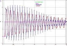
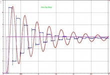
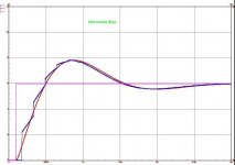
Attached are simulations of three cables. 10m DNM (CI 470) 10m Zip (CI 120) and 10m Isolda (CI 8). The mauve trace is the step input, the red trace is the lumped and the blue trace is the distributed R, L & C.
I will attach the circuit later as this lot fills the allocated attachment size limit.
Attached are simulations of three cables. 10m DNM (CI 470) 10m Zip (CI 120) and 10m Isolda (CI 8). The mauve trace is the step input, the red trace is the lumped and the blue trace is the distributed R, L & C.
I will attach the circuit later as this lot fills the allocated attachment size limit.
Attachments
Indeed..it's been entertaining watching this discussion.
After that, and in, order to get a lot of fun during all the summer, i propose several deep similar subjects.
-Tubes sound better than transistors.
-Fixing your amplifiers on golden cones makes them better.
-Discrete components sound better than integrated circuits.
-Numeric produce aggressive and cold sound. (Vinyl sound better than cds)
-Class D amps are only good for PA or cars. (they sound cold and cheap).
- Without Classe A, no salvation.
- The "sound" of the components.
To conclude with the best of all:
- Measurements means nothing. Listening is the only way. (And the contrary)
Last edited:
Scott
Ill repeat it. Its not a round trip. Its one way from the load to the source.
You said 100-200 reflections, think about it the "action" at the load starts with a 15ns delay all the subsequent steps are 30ns wide.
jneutron
I have phrased that as we do in Oz (uni WA). In UK speak, it is degree Bachelor of Engineering (Hons) top marks possible in the unit Low frequency transmission line theory. I don't know what it is in US speak.
I have phrased that as we do in Oz (uni WA). In UK speak, it is degree Bachelor of Engineering (Hons) top marks possible in the unit Low frequency transmission line theory. I don't know what it is in US speak.
Please, specify the conditions of the test. What amplifier? Scale of the signal (both level and time). Where the signal is taken. Charge characteristics. Lenght, capacitance and ohmic resistance of each cable, Signal with same charge and no cable. And, please, no simulations, but real measurements. Real world, as you says.Attached are simulations of three cables.
And, make my day, the same measure with a loudspeaker as a charge.
[edit]Why one ? Two different loudspeakers is more fun.
And two different amplifiers i will be in heaven.
Last edited:
Attached are simulations of three cables. 10m DNM (CI 470) 10m Zip (CI 120) and 10m Isolda (CI 8). The mauve trace is the step input, the red trace is the lumped and the blue trace is the distributed R, L & C.
I will attach the circuit later as this lot fills the allocated attachment size limit.
The first two do not predict your "slower response" glitch, they look like ringing around the desired level. Low pass them (like any real audio power amp would) and they will tend to look alike.
Please, please somebody send me the schematic of a nice 100W amplifier that makes the blue traces.
Last edited:
Scott
Thinking about it yes you must be right. I dont recall exactly the time delay but at the time of the experiment the delay was as predicted from the speed of signal propagation. In the intervening time I had forgotten the round trip so I was wrong in my example calculation assumptions but it doesnt change the principle nor what I saw ie the steps in the square wave front edge. Of course you do have to use a fast scope to see the staircase so square wavenplots produced in say mag reviews wouldnt show it. I think it was at least a 100MHz one perhaps even faster.
Need to repeat the experiment to establish the hard facts.
John Dunlavy
This might be of interest to a few people:
This might be of interest to a few people:
Date: Tue, 5 Nov 1996 13:08:50 -0500
From: 102365.2026@compuserve.com (Dunlavy Audio Labs)
To: bass@mcfeeley.cc.utexas.edu (bass group)
Subject: Cable Nonsense (Long)
Having read some of the recent comments on several of the Internet audio groups, concerning audible differences between interconnect and loudspeaker cables, I could not resist adding some thoughts about the subject as a concerned engineer possessing credible credentials.
To begin, several companies design and manufacture loudspeaker and interconnect cables which they proudly claim possess optimized electrical properties for the audiophile applications intended. However, accurate measurements of several popularly selling cables reveal significant differences that call into question the technical goals of their designer. These differences also question the capability of the companies to perform accurate measurements of important cable performance properties. For example, any company not possessing a precision C-L-R bridge, a Vector Impedance Meter, a Network Analyzer, a precision waveform and impulse generator, wideband precision oscilloscopes, etc., probably needs to purchase them if they are truly serious about designing audio cables that provide premium performance.
The measurable properties of loudspeaker cables that are important to their performance include characteristic impedance (series inductance and parallel capacitance per unit length), loss resistance (including additional resistance due to skin-effect losses versus frequency), dielectric losses versus frequency (loss tangent, etc.), velocity-of-propagation factor, overall loss versus frequency into different impedance loads, etc.
Measurable properties of interconnect cables include all of the above, with the addition of those properties of the dielectric material that contribute to microphonic noise in the presence of ambient vibration, noise, etc. (in combination with a D.C. off-set created by a pre-amp output circuit, etc.).
While competent cable manufacturers should be aware of these measurements and the need to make them during the design of their cables, the raw truth is that most do not! Proof of this can be found in the absurd buzzard-salve, snake-oil and meaningless advertising claims found in almost all magazine ads and product literature for audiophile cables. Perhaps worse, very few of the expensive, high-tech appearing cables we have measured appear to have been designed in accordance with the well-known laws and principles taught by proper physics and engineering disciplines. (Where are the costly Government Consumer Protection people who are supposed to protect innocent members of the public by identifying and policing questionable performance claims, misleading specifications, etc.?) --- Caveat Emptor!
For example, claiming that copper wire is directional, that slow-moving electrons create distortion as they haphazardly carry the signal along a wire, that cables store and release energy as signals propagate along them, that a final energy component (improperly labeled as Joules) is the measure of the tonality of cables, ad nauseum, are but a few of the non-entities used in advertisements to describe cable performance.
Another pet peeve of mine is the concept of a special configuration included with a loudspeaker cable which is advertised as being able to terminate the cable in a matter intended to deliver more accurate tonality, better imaging, lower noise, etc. The real truth is that this special configuration contains nothing more than a simple, inexpensive network intended to prevent poorly-designed amplifiers, with a too-high slew-rate (obtained at the expense of instability caused by too much inverse-feedback) from oscillating when connected to a loudspeaker through a low-loss, low-impedance cable. When this box appears at the loudspeaker-end of a cable, it seldom contains nothing more than a Zobel network, which is usually a series resistor-capacitor network, connector in parallel with the wires of the cable. If it is at the amplifier-end of the cable, it is probably either a parallel resistor-inductor network, connected in series with the cable conductors (or a simple cylindrical ferrite sleeve covering both conductors). But the proper place for such a network, if it is needed to insure amplifier stability and prevent high-frequency oscillations, is within the amplifier - not along the loudspeaker cable. Hmmm!
Having said all this, are there really any significant audible differences between most cables that can be consistently identified by experienced listeners? The answer is simple: very seldom! Those who claim otherwise do not fully grasp the power of the old Placebo-Effect - which is very alive and well among even the most well-intentioned listeners. The placebo-effect renders audible signatures easy to detect and describe - if the listener knows which cable is being heard. But, take away this knowledge during blind or double-blind listening comparisons and the differences either disappear completely or hover close to the level of random guessing. Speaking as a competent professional engineer, designer and manufacturer, nothing would please me and my company's staff more than being able to design a cable which consistently yielded a positive score during blind listening comparisons against other cables. But it only rarely happens - if we wish to be honest!
Oh yes, we have heard of golden-eared audiophiles who claim to be able to consistently identify huge, audible differences between cables. But when these experts have visited our facility and were put to the test under carefully-controlled conditions, they invariably failed to yield a score any better than chance. For example, when led to believe that three popular cables were being compared, varying in size from a high-quality 12 AWG ZIP-CORD to a high-tech looking cable with a diameter exceeding an inch, the largest and sexiest looking cable always scored best - even though the CABLES WERE NEVER CHANGED and they listened to the ZIP Cord the entire time.
Sorry, but I do not buy the claims of those who say they can always audibly identify differences between cables, even when the comparisons are properly controlled to ensure that the identity of the cable being heard is not known by the listener. We have accomplished too many true blind comparisons with listeners possessing the right credentials, including impeccable hearing attributes, to know that real, audible differences seldom exist - if the comparisons are properly implemented to eliminate other causes such as system interactions with cables, etc.
Indeed, during these comparisons (without changing cables), some listeners were able to describe in great detail the big differences they thought they heard in bass, high-end detail, etc. (Of course, the participants were never told the NAUGHTY TRUTH, lest they become an enemy for life!)
So why does a reputable company like DAL engage in the design and manufacture of audiophile cables? The answer is simple: since significant measurable differences do exist and because well-known and understood transmission line theory defines optimum relationships between such parameters as cable impedance and the impedance of the load (loudspeaker), the capacitance of an interconnect and the input impedance of the following stage, why not design cables that at least satisfy what theory has to teach? And, since transmission line theory is universally applied, quite successfully, in the design of cables intended for TV, microwave, telephone, and other critical applications requiring peak performance, etc., why not use it in designing cables intended for critical audiophile applications? Hmmm! To say, as some do, that there are factors involved that competent engineers and scientists have yet to identify is utter nonsense and a cover-up for what should be called pure snake oil and buzzard salve - in short, pure fraud. If any cable manufacturer, writer, technician, etc. can identify such an audible design parameter that cannot be measured using available lab equipment or be described by known theory, I can guarantee a nomination for a Nobel Prize.
Anyway, I just had to share some of my favorite Hmmm's, regarding cable myths and seemingly fraudulent claims, with audiophiles on the net who may lack the technical expertise to separate fact from fiction with regard to cable performance. I also welcome comments from those who may have other opinions or who may know of something I might have missed or misunderstood regarding cable design, theory or secret criteria used by competitors to achieve performance that cannot be measured or identified by conventional means. Lets all try to get to the bottom of this mess by open, informed and objective inquiry.
I sincerely believe the time has come for concerned audiophiles, true engineers, competent physicists, academics, mag editors, etc. to take a firm stand regarding much of this disturbing new trend in the blatantly false claims frequently found in cable advertising. If we fail to do so, reputable designers, engineers, manufacturers, magazine editors and product reviewers may find their reputation tarnished beyond repair among those of the audiophile community we are supposed to serve.
Best regards,
John Dunlavy
Ah...you have mis-interpreted my amusement.Indeed.
After that, and in, order to get a lot of fun during all the summer, i propose several deep similar subjects.
I am enjoying the attempts to discuss elegantly, the issue from both sided of the fence.
Both sides are missing the boat.
You are correct, assuming a prop delay of 15 nSec for the length.You said 100-200 reflections, think about it the "action" at the load starts with a 15ns delay all the subsequent steps are 30ns wide.
I agree with you. The ringing of the speaker line in that fashion will do nothing that the load can see.The first two do not predict your "slower response" glitch, they look like ringing around the desired level. Low pass them (like any real audio power amp would) and they will tend to look alike.
Why was the load put higher than the line??? What a messy model, and not consistent with the actuals..
Please, please somebody send me the schematic of a nice 100W amplifier that makes the blue traces.
I believe you meant magenta trace.
Why oh why is it anyone would assume that one needs nanosecond risetimes to have reflections on a two meter cable??
Cheers, John
jneutron
I have phrased that as we do in Oz (uni WA). In UK speak, it is degree Bachelor of Engineering (Hons) top marks possible in the unit Low frequency transmission line theory. I don't know what it is in US speak.
My question was meant to be: What is low frequency transmission line theory?
Cheers, John
Just what i said. And a quite fast amp to get such slew rates ;-)I think it was at least a 100MHz one perhaps even faster
Will ask some mosquito friend of mine if he can ear such frequencies. The one who complain about my tweeters.
Measurements of 12m DNM cable (420 ohms)
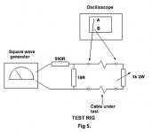
The first picture is the test setup. It doesn't matter what the source (amplifier) impedance is. Ten ohms was used for convenience to show the reflected signal at the source. The source impedance can be between zero ohms and infinity, and the results at the SPEAKER end are the same.
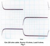
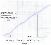
The second picture shows the slow rise time at the speaker end (as shown by a 100Mhz scope) and the third picture shows the reflection ripples at the speaker. The simulations are theory to show that there is a difference between lumped and distributed and the scope pictures show reality.
Following, on the next post, are scope pictures of impedance matched cable.
The first picture is the test setup. It doesn't matter what the source (amplifier) impedance is. Ten ohms was used for convenience to show the reflected signal at the source. The source impedance can be between zero ohms and infinity, and the results at the SPEAKER end are the same.
The second picture shows the slow rise time at the speaker end (as shown by a 100Mhz scope) and the third picture shows the reflection ripples at the speaker. The simulations are theory to show that there is a difference between lumped and distributed and the scope pictures show reality.
Following, on the next post, are scope pictures of impedance matched cable.
Attachments
Last edited:
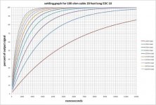
You would think the first thing you learn in transmission line theory would be when it is applicable.
"In many electric circuits, the length of the wires connecting the components can for the most part be ignored. That is, the voltage on the wire at a given time can be assumed to be the same at all points. However, when the voltage changes in a time interval comparable to the time it takes for the signal to travel down the wire, the length becomes important and the wire must be treated as a transmission line. Stated another way, the length of the wire is important when the signal includes frequency components with corresponding wavelengths comparable to or less than the length of the wire.
A common rule of thumb is that the cable or wire should be treated as a transmission line if the length is greater than 1/10 of the wavelength. At this length the phase delay and the interference of any reflections on the line become important and can lead to unpredictable behavior in systems which have not been carefully designed using transmission line theory."
How many orders of magnitudes is a 10 ft cable carrying 20khz away from this.
Last edited:
The theory of the reflexion of electrons on line extremities witch makes you able to build an echo chamber with only 5 meters of cables.My question was meant to be: What is low frequency transmission line theory?
I think it was at least a 100MHz one perhaps even faster.
So you need 100mhz scope to see effects in under 20khz signals? That should be a red flag.
Absolutely correct.You would think the first thing you learn in transmission line theory would be when it is applicable.
How many orders of magnitudes is a 10 ft cable carrying 20khz away from this.
That depends on the line to load ratio.
If the load matches the line on a 10 foot cable, the difference between what the load sees and what the source is trying to transmit, is separated by the propagation velocity times the length. That is all. For a standard coax, that would be about 20 nanoseconds of delay. NOTHING else happens.
If the load is two orders of magnitude lower in impedance than the line, this relationship no longer holds.
A common rule of thumb is that the cable or wire should be treated as a transmission line if the length is greater than 1/10 of the wavelength.
This common rule of thumb is based on the assumption that the load impedance is at or near the line impedance.
To attempt to use this simplistic rule of thumb on a grossly mismatched line to load setup is terribly erroneous.
Please learn the material first..your attemps at wit are straining a bit.The theory of the reflexion of electrons on line extremities witch makes you able to build an echo chamber with only 5 meters of cables.
Cheers, John
On the speaker point of view, the only interesting thing is Current.and the results at the SPEAKER end are the same.
Please answer this question: what will be the level of the current in the moving coil at such a frequency ?
And this one: Can-you apply hundred (or thousend) time this tension at such frequency and show us (via some laser interferometric measure) the cone movement of the fastest tweeter. ?
As long as it stays in the audio frequencies domain. Read and argue the previous, please. Please, learn (or consider) acoustic and mechanic material.Please learn the material first
That was the sens of my (i agree ) bad joke.
Last edited:
- Status
- Not open for further replies.
- Home
- General Interest
- Everything Else
- speaker cable myths and facts