And the difference between TL and lumped?
Tiny little ~40ns jaggies on top of same line, the picture is somewhere here. Of course there is the ~40ns delay at the beginning to prevent super-luminality.
Can't be.........would you post the model schematic please ?No, that's 3us group delay at 1kHz and 22us at 20kHz.
Can't be.........would you post the model schematic please ?
An ideal step generator, a series L of 454*20nH, a C to ground of 11.3*20pF, and a 1 Ohm resistor across the C. You can do it on paper and take the derivative of the phase by hand.
OK, so nothing even vaguely near the audio band?
Except for the delay which is all we are talking about I thought.
OK, but in the audioband that's just a simple LP filter formed from parasitics of the cable and the 1R load - so no surprise as to audioband group delay......... Such things would also obtain from ye olde Fred Davis paper IIRC............a series L of 454*20nH, a C to ground of 11.3*20pF, and a 1 Ohm resistor across the C. You can do it on paper and take the derivative of the phase by hand.
In my sims I didn't obtain audioband artefacts because I did not use such low loads as 1R. These effects have nothing to do with TL/lumped models, they are just down to cable parasitics.
OK I simulated latency similar to what has been described, based on the model Scott provided. It arises because the circuit is an audioband LP filter constructed from parasitic inductance of the selected cable and the 1R load resistor. If one arranges for the filter corner to be outside the audioband, unsurprisingly latency becomes negligible. This has nothing to do with TL behaviour, it is simply a property of LP filters like this..........so what is all the fuss about ?
Back To The Real World....
Fig 8 type twin speaker cables are not a constrained system such as coax is.
This means that each conductor of a twin cable generates an external time varying electromagnetic field, with magnetic field direction according to current direction.
Standard theory says that the two opposing send/return conductor current generated electromagnetic fields will tend to cancel.
The degree of cancellation is one factor that determines the total loop inductance value of a twin cable assy.
The degree of cancellation is largely determined by the send/return conductor spacing/symmetry.
The magnetic properties of material or items that intercept the magnetic fields radiating about each conductor will further modify the cancellation of the send/return current opposing magnetic fields consequently modifying cable assy inductance value.
These intercepting materials and items can have Ferromagnetic and/or Paramagnetic and/or Diamagnetic properties, and further can have time dependent properties.
Dan.
These intercepting materials and items can have Ferromagnetic and/or Paramagnetic and/or Diamagnetic properties, and further can have time dependent properties.
You're ready to start writing ad copy for audio scam companies!
As interesting as all this theory on Tl behaviour of speaker cables is, what
matters is does it have any sonic consequences in the audio band.
Is it possible to construct an experiment to find out one way or the other?
How about playing a mono signal (could even be music) into two separate
channels. Each channel has an equal length of a given cable into two different
resistive loads ie one "matched and the other "mismatched". Any difference at the load end could be measured differentially and analysed.
Ok if this wont work any other suggestions?
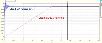
Here's result of a simulation which illustrates game-changing effect rise time has when considering cable behaviour in TL terms in response to a step change. Model is as Scott described, except load is 8R. Vertical is voltage at load, horizontal is time. Blue is for a 1ns rise time, red is for an audio bandwidth restricted risetime of 25uS.
For audioband risetimes, TL effects are obviously negligible.
For audioband risetimes, TL effects are obviously negligible.
Attachments
OK, now run the sim with an inductance in series with the load resistance (representative of the rising impedance that most speakers have from Lvc of the tweeter).
Here's result of a simulation which illustrates game-changing effect rise time has when considering cable behaviour in TL terms in response to a step change. Model is as Scott described, except load is 8R. Vertical is voltage at load, horizontal is time. Blue is for a 1ns rise time, red is for an audio bandwidth restricted risetime of 25uS.
For audioband risetimes, TL effects are obviously negligible.
I think you missed some of the background on this. It started with some studies that interchannel delays of as little as 5 usec are audible. I don't necessarily subscribe to any of that in free field listening (maybe head in vice listening). I just like the consistency of the math and physics, Zo, L, C, and speed of propagation are all linked and either way works the same.
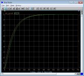
BTW your plot maximally obfuscates the issue, 8 Ohms just gives 1/8th the pulse delay maybe inconsequential so what. Audio BW (20kHz) pulse at 8 Ohms.
Attachments
Last edited:
Let me at it, haha.You're ready to start writing ad copy for audio scam companies!
Speaker cables routed against steel chair/stand legs etc can make an audible difference IME.
Ditto wrapping power and signal around tripod aluminium support poles of typical self powered or passive 2 way plastic PA speakers.
The difference is not 'staggering', but real none the less.
Dan.
What's going on in these audioband risetime models is everso simply just the parasitic inductance of the cable in series with the load, forming a low pass filter......... with audioband constrained risetimes there's no TL effect in play for all the reasons already set out. By choosing 1R for the load, you've arranged the filter to have debatable artefacts in the audioband. By choosing 8R for the load I arranged for them to be negligible........either way such effects will be thoroughly swamped by series inductance/complex impedance of real speakers in most cases - but the principle that TL effects are negligible is true no matter what the load impedance.I just like the consistency of the math and physics, Zo, L, C, and speed of propagation are all linked and either way works the same.
BTW your plot maximally obfuscates the issue, 8 Ohms just gives 1/8th the pulse delay maybe inconsequential so what. Audio BW (20kHz) pulse at 8 Ohms.
Last edited:
For audioband constrained risetimes, simulation shows no difference (versus R load)) to the simulated voltage waveform on the speaker terminals because the dominant extra inductance is within the speaker. Looking back into the cable, the speaker see a low impedance voltage source providing an audioband risetime signal, and this is what pretty much any load sees across the speaker terminals. Obviously internal to the speaker there is a LP filter which has a complex impedance and so current in the line lags applied ramp waveform, no surprises and no audioband interaction with the cable parasitics that simulation shows.OK, now run the sim with an inductance in series with the load resistance (representative of the rising impedance that most speakers have from Lvc of the tweeter).
For rf risetimes, simulation shows a significant differences (versus R load), such as extension of settle time, as TL effects apply and impedance increases with frequency.
I didn't see any surprises............
Dinki di, mate.
Dan.
Long ago, before the long trip in the yellow bus memory fades but i remember a man, a dusty man, a road warrior in fact that ate Dinki di and appeared to like it.
Oh wait, that was a movie;
https://www.youtube.com/watch?v=3LA5c0b4VeE
Yes. In fact, the difference in delay as a result of frequency dependent load impedance.Except for the delay which is all we are talking about I thought.
Yes, both are equivalent. For me, it is just a better way to envision what is going on.I think you missed some of the background on this. It started with some studies that interchannel delays of as little as 5 usec are audible. I don't necessarily subscribe to any of that in free field listening (maybe head in vice listening). I just like the consistency of the math and physics, Zo, L, C, and speed of propagation are all linked and either way works the same.
And shifting one channel universally across all frequencies will do nothing, as the listener position will dominate there.
It's when the program content causes a shift on one channel of some of the frequency content and not the other, that the image can go nuts.
jn
- Status
- Not open for further replies.
- Home
- Member Areas
- The Lounge
- Speaker Cable lifters or stands?