Hi Bryan,Thanks Dave. I'll remeasure today hopefully according to your info.
In answer to the mic question, I'm using a UMIK-1 with USB, and the correction file installed in REW.
I'm trying to recall the suggested cutoff for gated tweeter measurements, would .4ms be OK, or should it be a bit longer, .5? I seem to recall .4-.6 being the suggested range.
I've also added some internal damping to the enclosure, pretty modest but the least I would expect to use. I think I see some noticeable cab resonances in the first set of measurements I took, so hopefully this will tame things down a bit and make the crossover design less difficult.
Last question: I took impedance and T/S measurements with the Dayton DATS3, both on the bench and in the box. The bench numbers are closer to the Radian spec sheet, but wouldn't I want to use the measurements taken with the box?
In terms of setting the R marker to remove reflections from measurements (thus the gate window) - this explains it well and shows how to identify the first reflection:
https://drive.google.com/file/d/0B_...b_wTdB3s&resourcekey=0-RiCZWic1HLKw_QEIzjLwpQ
In terms of impedance measurements - self measurements are useful for the following:
1. Check if a driver has some manufacturing anomaly / rub or other resonance that the manufacturer graph doesn't show (or inconsistency between 2 drivers)
2. Check if there is an in cabinet resonance / reflection or something affecting the linearity of the driver which would be evident with small amplitude peaks in the impedance response
3. Check the tuning of a vented enclosure (impedance saddle / minimum between the 2 peaks and whether you are after optimal tuning with same height peaks, or under / over tuning as I call it).
I didn't mention crossover design? Why? Well - where we normally cross over speakers (anything up to 3 way) the enclosure alignment (which affects bass response) has little effect on the driver in box impedance. Therefore manufacturer impedance curves can be used for crossover design with reasonable closeness to reality. Obviously if you measure your inbox driver impedance, it's ideal, but not essential for effective crossover design IMHO.

Thanks again Dave, this is very helpful. Studying the VCAD manual when I have a few extra brain cells to spare - very steep learning curve, but it's somewhat intuitive in ways. My biggest anxiety is there's so much packed in there I don't know what I might be missing, so for now I'm using the KISS approach and will learn as I go. Feels like a dream where I suddenly find myself in the cockpit of an F-22, and everything is written in another language.
I don't have the impedance measurements in front of me right now, I bought a dedicated PC for all this stuff, stripped everything else out except the search engine. The measurements were pretty close to factory tests, but definitely altered by the enclosure, so I'll use my data. T/S on the other hand had some notable anomalies from Radian's numbers, not huge but significant, for example Qt moving from .38 (Radian) to .53 (mine, these numbers are rough recollections).
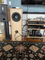
FWIW, here's my test enclosure:
I don't have the impedance measurements in front of me right now, I bought a dedicated PC for all this stuff, stripped everything else out except the search engine. The measurements were pretty close to factory tests, but definitely altered by the enclosure, so I'll use my data. T/S on the other hand had some notable anomalies from Radian's numbers, not huge but significant, for example Qt moving from .38 (Radian) to .53 (mine, these numbers are rough recollections).
FWIW, here's my test enclosure:
Attachments
Last edited:
Well, I've been off the trail for a few weeks due to crazy summer work demands, but I'm moving along again, and would like to post some questions.
I'm still reading Scott Hinson's work and it's fantastic, learning a lot. Also trying to study the REW and Vituix manuals. It's difficult to retain a lot of this info when I'm not applying it as I go, but you've got to start somewhere!
I took a second round of measurements yesterday, and plan to do another round tomorrow, trying to refine the process as much as I can. Yesterday did NF/FF in our largest room, but having the speaker sitting on the floor really constrained my gating window, so I'm going to go outside tomorrow and at least get the speaker a few feet off the ground, hoping to get closer to 5ms for my window (at 1m indoors it's only 2.5ms for the floor bounce)
The more I learn, the less I know. Based on Dave's instructions above, and those of Mr Hinson, I took NF woofer, FF woofer (1m), FF tweeter, and port with the mic flush to the outside of the baffle (not inserted). Before I export from REW to Vituix, I need to do the following, if I'm correct - merge the NF/FF woofer curves, using the lower portion of the NF(below 400hz) and the upper end of the gated FF (above 400hz). Next, I need to incorporate the port curve somehow. Then I will need to attenuate the tweeter, but I'm pretty sure I do that later in the xover design in Vituix.
Here are my questions:
1. I assume that my standard for SPL is the two measurements taken at 1m, this is my default level. So when I splice the two woofer curves, I'll be attenuating the woofer NF to match levels with the FF. If this is correct, can I do it with trace arithmetic in the ALL SPL window?
2. Once I have a final woofer curve, how do I deal with the port? I ask this because the port is also being picked up by the 1m woofer measurement, although it's probably at a lower level than it would be at a real listening position, say 2 meters or more. Do I merge the port curve with the final woofer plot?
3. I'm really lost on the baffle correction. I know there is a tool in Vituix, can I wait until I'm in there to add the compenstaion, or should I do it in REW, and if so, when and how? There are so many ways to combine measurements, adding, subtracting, multiplying, averaging, I'm pretty lost here, and any advice is most appreciated.
Thanks in advance, I'm afraid there will be more questions! And I really am reading and trying to answer these questions myself, but every time I get close to an answer I end up with 3 more questions. I'd really like to do things properly and start on solid ground, I figure I can tweak the crossover later and play with interior stuffing a bit if there's some cleaning up to do during dress rehearsal in the final cab's.
Bryan
Here is my first dilemma - I've summed the port with the nearfield woofer measurement, in the first pic the port is dialed down -6.4db to align better with the woofer. In the second I dialed WAY down to -12db just to see what the difference would be. I don't understand where that nasty null is coming from at 60hz, does anyone have an idea?


OK, so I went out and bought a piece of 4" ABS to play with port tuning, and I also played with some fill in the cabinet to tame that 150hz resonance. I took sweeps at 34hz, 38, 40, and 42, with and without the extra damping. Below is a graph showing the NFwoofer and the port tuned to 34hz with damping, and the summed response using trace arithmetic in REW. I'm shocked at the difference, and that the 70 hz null has disappeared. I think what might have happened is that in the earlier measurements I used the Alignment Tool and summed the two there after reducing the port by 6.4db. I think Trace Arithmetic is the correct way to do it, as I was advised. I'm nervous about the 8db rolloff from 200hz down to 34, but hopefully I can compensate later with some baffle step work? Here's the graph:
