Some answers to your wondering why the differences or preference of one table to the next:
- In my experience all distortions add to the music. The additive effects can be very good, but are due to energy storage and release. These distortions usually become part of the sonic signature of the table (or almost any audio piece for that matter) because they are coupled to the turntable/plinth system.
- The liveliness apparent in the TD124 could be attributed to the material used for it's plinth, and the total mass of that and/or other materials.
- The same can be said for that of the SP10MkII, if in the Obsidian base vs say a wooden one or alternate material or combination of materials. The total mass whether a combination of materials is still important.
- My thoughts regarding this is that if both tables were placed in similar plinths (same construction and total mass , down to possible constituent materials) you would find the differences to be reduced. If you can minimized the sound of the idler wheel, then the differences should be reduced again
- Based on my experiences with my old Oracle and an old Dual 1214, I can say that the old Dual holds it own, even without minimizing the effects of the idler wheel
from "justaguy" 🙂
To begin with my comments were meant as observations. Sentences prefixed with a question mark were offered in the rhetorical sense. And also posed as something for me to address as time goes on.
I am aware of certain dogmatic points of view circulating around the web having to do with turntable drive systems and whether or not said systems contribute to the overall temperament/character of a turntables' output or if it isn't just a matter of matching a given TT to a proper plinth to alter its character.
At this point in time I tend to view the design of the drive to be the dominant feature in determining a turntable's signature sound. And that there will be a signature sound. However it will be interesting to see how much of a character change there is using different plinth designs. I will try at least one more design before committing to a paint job on the plinth.

I have experimented a little bit with my TD124 by listening to it in different plinths. Currently it is in heavy slate. But I have listened to it in a sturdy but open box style plywood support. With mushroom isolators. Without mushroom isolators. Overall, I heard the same signature sound coming out of that TT in any of those 4 configurations. However, I thought there was a slight bit greater musical energy coming from the Thorens when parked in the open box plinth and on mushrooms. But it was also the noisiest in terms of background residual noise. In the slate, it retained 'most' of its energetic output but with improvements in reduction of background noise and improvements in detail retrieval. Etc.
It's early, but I tend to think that once certain criteria are met, like platter and bearing performance, and given equal arms/carts/downstream components, motor performance is a prominent part of any drive train and will contribute --or detract -- from the listening experience in an obvious way.
-Steve
Investigations we've been doing with the help of Paul R over on PFM would seem to back up that drive and suspension/or otherwise largely define the sound of most decks.
Turntable speed analysis - Page 6 - pink fish media
Turntable speed analysis - Page 6 - pink fish media
Investigations we've been doing with the help of Paul R over on PFM would seem to back up that drive and suspension/or otherwise largely define the sound of most decks.
Turntable speed analysis - Page 6 - pink fish media
Thanks for posting that. I've been reviewing that thread from page 6 forward. If I understand correctly, they are plotting a constant test tone from a test record and measuring for wow/flutter.
If I'm correct in that assumption, the test results are useful in comparison against different turntables and how they measure the same test tone.
What I'd like to see is a test tone that includes a sudden increase in modulation at a lower frequency. Something in the bass, and then again something in the mids. A sudden increase in modulation in the midrange. This would be to test for the effects of modulated stylus drag on platter speed. Say, compare different turntables for how much, and for how long the speed variation occurs.
But then I don't even know if there is such a test for making that kind of measurement. But the wow/flutter testing on constant pitch tones are still useful.
And they are using Fickert's Ultimate Analog test software?
Adjust+ - Home
-Steve
Steve...my comments about my comments...
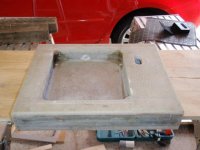
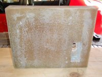
I agree with you. I guess I was answering an rhetorical questions or replying to your comments. It seems we are on the same page. Where did you source your slate from? That is currently the largest issue for me: accessing the raw slate. I've tried counter top shops, etc. Another option may be soapstone (if they can make sinks out of it, I'm sure a plinth could be made easily enough).
stew
Hi Stew.
The slate I have I acquired from J.Weiss at Oswalds Mill Audio. My setup is one of two prototypes from the first slate plinths produced for the TD124 there. As such it does not resemble the external appearance of that firm's current product. But the internal cutouts (by cnc water-jet) were made from a cad file I produced. I believe they still use a version of that file....perhaps with modifications/refinements.
I haven't done any further work on that plinth. One of these days, when certain planets align, I'll rework the surfaces and edges of that plinth into a slightly different appearance. But that's for another day. Right now I'm thinking about the SP10 mkII and how to learn from it what I can learn.
I haven't tried to access slate from any other source. Flooring and roofing pieces that you can find in the home improvement stores won't do. But the same slate quarry that produces those pieces will likely also produce counter-top slate of a much thicker dimension. The limit for thickness might be somewhere around 2 inches....depending on the machinery available to work the raw product at the quarry. At least that was a limit imposed on the two pieces of slate that I have. Maximum thickness available from that quarry at the time. Just under 2 inches. But that was in 2007/2008.
So I would go to the source; an actual slate quarry. Also, some of the guys over at Lenco Heaven have found their own sources for heavy pieces of slate. I would search over there if you are serious about a diy slate plinth.
For myself I don't know that I will do another slate plinth. Other than keeping and perhaps reworking the one I already have. Instead, I intend to experiment with different woods over time. Right now I tend to think that stacked Baltic Birch ply can sound very musical. Just an opinion not verified by any method other than by listening.
-Steve
Last edited:
Revive the SP10 mkII plinth thread. My experience.
I recently found this thread and thought I might contribute my experience. I have an extensive background in vinyl replay systems. I owned 2 Garrard 401's in the early '70's and a Linn LP12 from 1975-2003. In between I have owned various Thorens, and currently I am re-plinthing a TD125 mk1. I have owned various tonearms including Decca International unipivots, SME 3009's, Stax UA7, Rega 250, 300, Michell Special 250, and currently 2 SME IV.
Since 1999, my table of choice has been the SP10 mk2. All of my previous tables have been plinthed by me and I feel I have learned a fair bit of useful information about materials applied to plinth systems. To cut to the chase, the three important parameters for a plinth are mass, stiffness and damping. Of these the hardest to get right is damping.
http://qualia.webs.com/dampingfactor.htm
It is best to use materials inherently well damped rather than apply a damping treatment. Densified wood (Panzerholz etc) measure well for all three parameters but it is almost unobtainiun in my neck of the woods and incredibly expensive. I have built SP10 plinths from timber products, engineered stone, Corian and finally, isopthalic fibre-reinforced polyester resin.
http://qualia.webs.com/apps/profile/71866842/
The resin plinth is the best so far but is extremely time and labour intensive to produce. The ply fibre layers are laid down in resin over days. The curing process generates considerable heat, so cannot be rushed.
http://qualia.webs.com/apps/forums/topics/show/3538558-polyester-resin-and-bentonite?page=1
Regarding some of the comments from previous posts, in my experience, for mechanical systems (cartridges, tonearms, plinths, loudspeakers), the better the damping, the more natural is the reproduction. Less well damped components can sound exciting, snappy and vivid, but long term critical listening usually reveals an unnatural quality. For example the SME V/IV tonearms are sometimes criticised as boring, but they are just accurate in my experience.
Attachments

Yes. Thanks for posting on an interesting topic; plinth materials.
I was reviewing qualia webs for a damping test on 'fiber reinforced phenolic resin' but did not see that material mentioned. It is an older plastic material available with different fabrics/materials that occasionally gets mentioned among TT diy'ers but....
Have you considered removing the SP10 mkII drive components from the aluminum chassis and into an alternate housing?
-Steve
Hi Steve. My first serious SP10 mkII plinth was the Corian one in around 2000. I discovered the "bearing drain" back then and the TT is bolted through the full thickness and pulled down so that the main bearing is clamped down onto 2 layers of 3 mm lead sheet lining sandwiched with the plinth base. This lasted for ten years when I acquired an SME IV to replace the souped up Rega RB300. The higher resolution of the SME lead me to construct a new plinth from an engineered stone "Caesarstone" commonly used for kitchen benchtops. The resulting plinth was massive (34 kg), stiff but poorly damped by empirical tests. I managed to tame the 20 mm thick base by applying constrained layer damping to both surfaces of the base, with two 3 mm aluminium sheets sandwiching the engineered stone with a polyurethane damping layer on each side. This was an improvement. I discovered the audio qualia site and have a good friend and fellow SP10 mkII owner, who happens to be an expert with fiberglass resins. We did some empirical tests and were very impressed with the results. We went forward with the resin/fiber SP10 plinths, which required mold construction and working with quite toxic materials. A surface filler compound is applied and then sanded to very flat finish. Then a high quality auto spray coat is applied. The results justified the effort. The mass is approx 18 kg. Total thickness is 90 mm. Stiffness is beyond reproach and damping excellent. Where I notice the improvement is firstly in human voice reproduction. It just sounds so natural with the SME IV and various moving coils. All frequency bands are as good as I have experienced in my system and listening room.
As for removing the parts from the chassis, I have always removed the brake. I have three SP10's, two in use and one spare. I have been toying with removing the chassis from the spare and installing the parts in a resin/fiber plinth. Just an idea at the moment. If I carry through results will get reported here.
As for removing the parts from the chassis, I have always removed the brake. I have three SP10's, two in use and one spare. I have been toying with removing the chassis from the spare and installing the parts in a resin/fiber plinth. Just an idea at the moment. If I carry through results will get reported here.
Attachments
Very nice.
Have you thought about casting one in pre-cast concrete and then just applying a resin outer skin in order to effect the finish ?
Have you thought about casting one in pre-cast concrete and then just applying a resin outer skin in order to effect the finish ?
Concrete does not work, though I accept that experiment with various strength of mix, sand types and sizes and interleaves of varying types may just find a golden mix!
I have found that solid welsh slate interleaved with alloy sheet does an excellent job. But I stripped my SP 10 of its electronics and placed them out-board so that only the motor is plinth mounted. I also use a bearing sink and got rid of all brakes etc back when I ran the motor with backplate in the official Technics all-Obsidian plinth.
I have found that solid welsh slate interleaved with alloy sheet does an excellent job. But I stripped my SP 10 of its electronics and placed them out-board so that only the motor is plinth mounted. I also use a bearing sink and got rid of all brakes etc back when I ran the motor with backplate in the official Technics all-Obsidian plinth.
The fiber/resin is more than just a cosmetic finish. Go to the audio qualia link in my original post where damping is extensively discussed. In fact I have tried concrete plinths when I knew much less than now, way back in the early 1970's on a pair of Garrard 401's I bought new. The plinths were very heavy and stiff but again poorly damped. The 401's sounded terrible in these plinths. It put me off idler drives. My experience has convinced me that concrete is a very poor material for plinths.
Just think of how sound transmits through a bare concrete floor or wall.
The engineered stone has a significant resin content (5-10%) but this still needed double constrained layer damping.
Just think of how sound transmits through a bare concrete floor or wall.
The engineered stone has a significant resin content (5-10%) but this still needed double constrained layer damping.
Last edited:
Seems like I've got a bit to learn.
I was driven way from the Vinyl route by the advent of CD.
I did purchase a Technics SP1200 MkII a few years ago but in its standard form I was again driven away from vinyl.
I was driven way from the Vinyl route by the advent of CD.
I did purchase a Technics SP1200 MkII a few years ago but in its standard form I was again driven away from vinyl.
To kick this thread along some more, here are some of my thoughts on plinth construction and materials. These comments are addressed to the SP10 mkII, which is the DD I know best. My best effort over a 15 year span, is the fiber/resin plinth. Approximately 60 layers of chopped glass fiber are laid down in resin as 90 degree ply layers, a few layers at a time, and left to cure between layers. The curing process generates considerable heat, and there is a risk of heat damage and even fire if too much resin is used at one time. It takes about 2 days to lay down a complete plinth in a mold with the recesses built in (you don't want to cut or grind fiber glass, believe me. The fibers are very hard on tools and the dust horrendous). I came on the polyester resin when I noticed that the dried residue in the bottom of tins, was very hard yet did not ring when chiseled it out for test. This got me thinking and an ... aha moment. With the fiber re-inforcing, it is a very good material, though slow to work with.
Now here is some speculation as to why this type of plinth (laminated layers in a damping matrix) works well with good high torque DD. As has been pointed out earlier in this thread and elsewhere, torque reaction has to be dealt with. Assuming perfect motor and bearing for the moment, with the concentric motor. all turntable induced motion should be in a horizontal plane, including the torque reaction. A layered plinth is perfectly configured to dissipate the torque reaction as shear in the damping layers. This may have some bearing on the popularity of layered baltic pine plywood and certain slates. I have never used these materials for plinths or listened to them so I have no first hand experience of their performance. However, my comments do rely on effective damping layers and in the baltic ply, this is the glue. I'm not sure what natural adhesive is involved in the slate. An added bonus is that a layered material also acts as constrained damping, and will convert vertical vibration from non-perfect bearing and motor, to shear in the damping layer and be dissipated.
Getting back to the SP10 mkII and the effect of different platter masses. Now Technics warn severely against using the motor without the platter. Any observations about the motor behaviour without the platter, are to be discounted IMO. However, Technics do discuss the SP10 mkII performance under an extreme overload, which implies the SP10 mkII is perfectly happy with platters of greater mass than the stock 2.9 kg. One of the photos in my first post shows the SP10 mkII in use with a copper/carbon fiber mat. I use this in conjunction with a peripheral ring and a 850 gm record weight. The total extra weight of these is exactly 5 kg by my scale. Total platter plus extras is 8.9 kg. Since I have 2 SP10 mkII in use, I connected a splitter for the wired remote control switch I possess, so I could synchronise switch on and observe the time to visual stabilisation for the 8.9 kg mass versus the standard 2.9 kg plus rubber mat and clamp.
There was a minor difference to speed stabilisation (about 15% from my recollection) which is not surprising given the much increased moment of inertia), but an increase from 25% of a revolution to 30% is not an issue for me. Not all DD's are equal though. The same test on an SL1210 showed a much longer time to speed stabilisation. The SL1210 motor has noticeably less torque. I think Technics got the control system for the SP10 mkII pretty right. A well designed control system is insensitive to a wide range of parameter variation. For example, a large passenger airline must behave approximately the same in controlled flight when fully loaded with fuel, passengers, and cargo, as when unloaded and low on fuel. This is part of the design and is quantifiable.
lazy is as lazy does

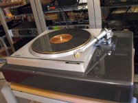
It has been a while since I took the SP10 mkII down from its perch amidst the other audio gear and parked it into a shelf on a rack in my study/computer room. In that mean time I have been enjoying the TD124.

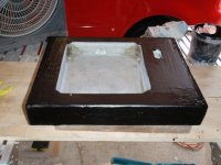
Above photo: #2729 standing in slate. Zeta tonearm with vdh silver wire in an Incognito made harness. A Denon DL-103R mounted within a Uwe Panzerholz body...and with SoundSmith Ruby cantilever/fine line stylus. Sends signal into a pair of Sowter 1:10 step up trannies. Then into a Wright WPP100C phono preamp (with adjustable gain pots).
At this point I consider the TD124 a more enjoyable deck to spin vinyl on than I did the SP10 mkII.
It may not be fair to describe the SP10 mkII as being audibly inferior to the Thorens. All I did with the SP10 mkII is observe that it appeared to be 100% operational and then build a stacked-layer baltic birch ply plinth for it to mount into. Stuck it in the plinth. Mounted the same arm/cartridge I'd been using on my Thorens to the Technics. I used the same step up trannies and phono stage as with the Thorens. With that much in place I simply began listening to vinyl for a couple hundred records or so. A few months worth.
What I heard from this old Technics was impressive. Using the same arm/cart/signal chain as with the Thorens, the Technics gave a deeper more detailed view into the record groove. Articulation of musical detail and nuance became more precise. Think of those brief musical passages that flow by like a blur. But now you hear/see them in crisp detail.
The Technics also seemed to not get in the way of the flow of the music. To make use of an old Linnie term from decades past, the SP10 mkII was giving excellent PRaT. (pace, rhythm and Timing)
Musical genre's listened to included rock, jazz, classical, baroque, ancient, folk, folk-rock..... and on and on. I'd have to say that the SP10 mkII excelled at large scale symphonic music as well as with chamber music or even string quartets.
I was favorably impressed with its ability to get the articulation, pace, tone and timbre of my collection of Beethoven string quartets as performed by The Quartetto Italiano. This music won't be to everyone's personal taste, but it can be addictive once it hooks you. The Technics played this better than anything I've heard in my room.
Then there is Charles Munch and the Stuttgart Chamber Orchestra playing Bach. (circa 1960 - 1962 on London FFSS) The SP10 mkII reproduced this Bach Fugue music making it sound like the internal workings of a finely jeweled Swiss watch. Just like it should.
Rock and jazz were listened to in abundance. I can't say that it disappointed my expectations in any way.
Yet, after stating the above, I concluded that in the comparison as it was, I still preferred the TD124 (refurbished and standing on heavy slate) over the younger Technics deck. Clearly, both decks are produced to very high manufacturing standards. The Technics enjoys an advantage of clearly superior speed pitch control and with extremely low wow/flutter test results. And some of the most impressive signal to noise readings ever...
The Thorens, while not among the best at low flutter/wow, does lay down a rock solid stable speed (once you get that part sorted 😉)..... and its signal to noise capability is far better than most people think. Then,... it goes on to do something that I've yet to hear any direct drive do. It can make the more dynamic parts of the music leap out of the speakers at you with sudden and surprising forward presence. I believe this performance attribute to be a feature of its idler drive design. And also I suspect that other idler driven turntables would also be able to produce this effect. But the Thorens can do this while producing a large, open and detailed sound field that most people don't expect from an idler driven TT. Must be the belt/idler architecture inherent in the thorens at play here.
I could further qualify the Thorens as being better at fine musical detail than some might expect. Excellent, in fact. And it can produce a very large sometimes holographic sound field. I prefer it for playing jazz and rock. It has a more visceral and gutzy, slammy reproduction here. It delivers the parts of the music that imprints itself upon the listener's soul. Really, I'd say that that is what the TD124 has. Soul.
In comparison, I would characterize the Thorens as reproducing with a somewhat "organic" character while the Technics, very capably reproduces with a somewhat "analytic" character. Both of these character traits are desirable. But I've yet to hear a single player that can get both together in a single whole.
So this,....for me, is further evidence that for different records, one might want different record players.😎
But where does this assessment leave me and my SP10 mkII project?
My answer is that I'm not yet finished with it.
Here's how it is:
1) I'm not crazy about the looks of the SP10 mkII. I think its boxy and rectangular aluminum plinth is...well, too boxy and rectangular.
2) And then there is the matter of fitting a tonearm. Yes, you can fit just about any 9 inch tonearm up to it....perhaps with some necessary mods to the tonearm.
The Zeta, with its 228.6mm effective length is among the shorter 9 inch tonearms out there, and I was able to make that work. Admittedly, the Zeta had its arm tube almost in contact with the frame that holds the pivot bearings when going into the dead wax of any record. But there was just enough clearance for the Zeta to track into the dead wax and so it did work. Although the cue lift bar on it was a bit short on reach when the tonearm was tracking into the lead-out. My solution was to produce another cue bar, a longer one, out of carbon fiber, adhere some plate rubber onto it and use that as the cue lifting bar while the Zeta was mounted to the SP10 mkII. Problem solved.
But then it still looked wierd. Visually and functionally, 9 inch tonearms are just too short for this large chassis. It makes one look toward 12 inch tonearms as the obvious solution. But there we go spending more money.....again.
3) Right. Technics designed the deck around their 10 inch effective length tonearms...of which there are some notable models to be found. My problem is that no matter how well regarded these arms may be, I just don't like the looks of them. EPA 100. EPA 500.
I guess that's just my personal taste. So here I am, not liking the appearance the the SP10 mkII but being favorably impressed with its sound quality.
What to do.......
Next step is to remove the motor unit and electronics boards, switches and strobe from the aluminum chassis and put the platter and motor into an alternate plinth of my own design. The electronics boards will go in another separate project box. The new design will accommodate 9 inch tonearms easily. In particular, I have a Graham 2.2 tonearm waiting for a decent enough record player to be matched up to. To go with the Graham I have an Ortofon MC Jubilee cartridge that mates well to it. So the idea is that a very accurately driven platter, that of the SP10 mkII, provides the drive for a tonearm and cartridge capable of very good detail extraction,... if a little short on dynamic slammy-ness. Perhaps the mutually analytic character of both the sp10 mkII drive and the Graham will combine to produce a spectacular result that looks way, way deep into the record groove and extracts the most minute detail in a chrystal clear holographic manner. Wouldn't that be something! I wonder if it will.
More about that in the next installment. For now I need to get back to my cad program and finish my first sketch of the new plinth.
later,
-Steve
PS: below are some more SP10 links I found around the web.
Updated Technics SP10 quartz PLL drive
http://www.edsstuff.org/dd_museum.pdf
Turntable Forum • Alternate SP-10 plinth design?
It has been a while since I took the SP10 mkII down from its perch amidst the other audio gear and parked it into a shelf on a rack in my study/computer room. In that mean time I have been enjoying the TD124.
Above photo: #2729 standing in slate. Zeta tonearm with vdh silver wire in an Incognito made harness. A Denon DL-103R mounted within a Uwe Panzerholz body...and with SoundSmith Ruby cantilever/fine line stylus. Sends signal into a pair of Sowter 1:10 step up trannies. Then into a Wright WPP100C phono preamp (with adjustable gain pots).
At this point I consider the TD124 a more enjoyable deck to spin vinyl on than I did the SP10 mkII.
It may not be fair to describe the SP10 mkII as being audibly inferior to the Thorens. All I did with the SP10 mkII is observe that it appeared to be 100% operational and then build a stacked-layer baltic birch ply plinth for it to mount into. Stuck it in the plinth. Mounted the same arm/cartridge I'd been using on my Thorens to the Technics. I used the same step up trannies and phono stage as with the Thorens. With that much in place I simply began listening to vinyl for a couple hundred records or so. A few months worth.
What I heard from this old Technics was impressive. Using the same arm/cart/signal chain as with the Thorens, the Technics gave a deeper more detailed view into the record groove. Articulation of musical detail and nuance became more precise. Think of those brief musical passages that flow by like a blur. But now you hear/see them in crisp detail.
The Technics also seemed to not get in the way of the flow of the music. To make use of an old Linnie term from decades past, the SP10 mkII was giving excellent PRaT. (pace, rhythm and Timing)
Musical genre's listened to included rock, jazz, classical, baroque, ancient, folk, folk-rock..... and on and on. I'd have to say that the SP10 mkII excelled at large scale symphonic music as well as with chamber music or even string quartets.
I was favorably impressed with its ability to get the articulation, pace, tone and timbre of my collection of Beethoven string quartets as performed by The Quartetto Italiano. This music won't be to everyone's personal taste, but it can be addictive once it hooks you. The Technics played this better than anything I've heard in my room.
Then there is Charles Munch and the Stuttgart Chamber Orchestra playing Bach. (circa 1960 - 1962 on London FFSS) The SP10 mkII reproduced this Bach Fugue music making it sound like the internal workings of a finely jeweled Swiss watch. Just like it should.
Rock and jazz were listened to in abundance. I can't say that it disappointed my expectations in any way.
Yet, after stating the above, I concluded that in the comparison as it was, I still preferred the TD124 (refurbished and standing on heavy slate) over the younger Technics deck. Clearly, both decks are produced to very high manufacturing standards. The Technics enjoys an advantage of clearly superior speed pitch control and with extremely low wow/flutter test results. And some of the most impressive signal to noise readings ever...
The Thorens, while not among the best at low flutter/wow, does lay down a rock solid stable speed (once you get that part sorted 😉)..... and its signal to noise capability is far better than most people think. Then,... it goes on to do something that I've yet to hear any direct drive do. It can make the more dynamic parts of the music leap out of the speakers at you with sudden and surprising forward presence. I believe this performance attribute to be a feature of its idler drive design. And also I suspect that other idler driven turntables would also be able to produce this effect. But the Thorens can do this while producing a large, open and detailed sound field that most people don't expect from an idler driven TT. Must be the belt/idler architecture inherent in the thorens at play here.
I could further qualify the Thorens as being better at fine musical detail than some might expect. Excellent, in fact. And it can produce a very large sometimes holographic sound field. I prefer it for playing jazz and rock. It has a more visceral and gutzy, slammy reproduction here. It delivers the parts of the music that imprints itself upon the listener's soul. Really, I'd say that that is what the TD124 has. Soul.
In comparison, I would characterize the Thorens as reproducing with a somewhat "organic" character while the Technics, very capably reproduces with a somewhat "analytic" character. Both of these character traits are desirable. But I've yet to hear a single player that can get both together in a single whole.
So this,....for me, is further evidence that for different records, one might want different record players.😎
But where does this assessment leave me and my SP10 mkII project?
My answer is that I'm not yet finished with it.
Here's how it is:
1) I'm not crazy about the looks of the SP10 mkII. I think its boxy and rectangular aluminum plinth is...well, too boxy and rectangular.
2) And then there is the matter of fitting a tonearm. Yes, you can fit just about any 9 inch tonearm up to it....perhaps with some necessary mods to the tonearm.
The Zeta, with its 228.6mm effective length is among the shorter 9 inch tonearms out there, and I was able to make that work. Admittedly, the Zeta had its arm tube almost in contact with the frame that holds the pivot bearings when going into the dead wax of any record. But there was just enough clearance for the Zeta to track into the dead wax and so it did work. Although the cue lift bar on it was a bit short on reach when the tonearm was tracking into the lead-out. My solution was to produce another cue bar, a longer one, out of carbon fiber, adhere some plate rubber onto it and use that as the cue lifting bar while the Zeta was mounted to the SP10 mkII. Problem solved.
But then it still looked wierd. Visually and functionally, 9 inch tonearms are just too short for this large chassis. It makes one look toward 12 inch tonearms as the obvious solution. But there we go spending more money.....again.
3) Right. Technics designed the deck around their 10 inch effective length tonearms...of which there are some notable models to be found. My problem is that no matter how well regarded these arms may be, I just don't like the looks of them. EPA 100. EPA 500.
I guess that's just my personal taste. So here I am, not liking the appearance the the SP10 mkII but being favorably impressed with its sound quality.
What to do.......
Next step is to remove the motor unit and electronics boards, switches and strobe from the aluminum chassis and put the platter and motor into an alternate plinth of my own design. The electronics boards will go in another separate project box. The new design will accommodate 9 inch tonearms easily. In particular, I have a Graham 2.2 tonearm waiting for a decent enough record player to be matched up to. To go with the Graham I have an Ortofon MC Jubilee cartridge that mates well to it. So the idea is that a very accurately driven platter, that of the SP10 mkII, provides the drive for a tonearm and cartridge capable of very good detail extraction,... if a little short on dynamic slammy-ness. Perhaps the mutually analytic character of both the sp10 mkII drive and the Graham will combine to produce a spectacular result that looks way, way deep into the record groove and extracts the most minute detail in a chrystal clear holographic manner. Wouldn't that be something! I wonder if it will.
More about that in the next installment. For now I need to get back to my cad program and finish my first sketch of the new plinth.
later,
-Steve
PS: below are some more SP10 links I found around the web.
Updated Technics SP10 quartz PLL drive
http://www.edsstuff.org/dd_museum.pdf
Turntable Forum • Alternate SP-10 plinth design?
Last edited:
bold moves....
So here's the thing; This TT was working perfectly. Now I've gone and disassembled it...😱


😱


Here's a clue. Date on Motor: June 22, 1976.


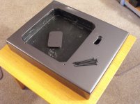
Every screw. Every part is tucked away in plastic ziplock bags according to assembly order. I think I'll find some old computer anti-static bags for those pcb's. I'd hate to kill this thing while it is in storage.

Whew! It came apart logically. I think I'll find a small box for that motor. To summarize, disassembly was composed of several pcb's that plug into each other and pulled apart without any difficulty. Reassembly should be as logical, except it won't be going back into the same chassis....😎
I didn't see any burnt capacitors but that doesn't mean they're all healthy. If anyone recognizes anything interesting, I'd appreciate your comments.
-Steve
So here's the thing; This TT was working perfectly. Now I've gone and disassembled it...😱
😱
Here's a clue. Date on Motor: June 22, 1976.
Every screw. Every part is tucked away in plastic ziplock bags according to assembly order. I think I'll find some old computer anti-static bags for those pcb's. I'd hate to kill this thing while it is in storage.
Whew! It came apart logically. I think I'll find a small box for that motor. To summarize, disassembly was composed of several pcb's that plug into each other and pulled apart without any difficulty. Reassembly should be as logical, except it won't be going back into the same chassis....😎
I didn't see any burnt capacitors but that doesn't mean they're all healthy. If anyone recognizes anything interesting, I'd appreciate your comments.
-Steve
Now let's take a peek inside the motor.
At the bottom of the bearing housing I see a fluted cap that holds the thrust ball. It appears to be of the kind that threads on. Anyone ever remove that part?


Bearing thrust pad is held to the shaft. If I think about it, that seems like a good idea. The plastic thrust will filter vibes coming off the thrust .....rather than the other more standard practice of having the thrust ball in direct contact with the shaft providing direct transfer of thrust rumble into the shaft. Like in a TD124.


There's a bearing ball at the bottom of the housing to provide thrust. I can see it when I shine a pencil thin flashlight down into the bearing housing. The ball shows no evidence of damage from that view, but I'd like to get the thing out for close examination / replacement. It will not be extracted with a magnet. I suspect it is held captive but won't know this 'til I remove the other end of the housing.
That will be in the next installment.
-Steve
At the bottom of the bearing housing I see a fluted cap that holds the thrust ball. It appears to be of the kind that threads on. Anyone ever remove that part?
Bearing thrust pad is held to the shaft. If I think about it, that seems like a good idea. The plastic thrust will filter vibes coming off the thrust .....rather than the other more standard practice of having the thrust ball in direct contact with the shaft providing direct transfer of thrust rumble into the shaft. Like in a TD124.
There's a bearing ball at the bottom of the housing to provide thrust. I can see it when I shine a pencil thin flashlight down into the bearing housing. The ball shows no evidence of damage from that view, but I'd like to get the thing out for close examination / replacement. It will not be extracted with a magnet. I suspect it is held captive but won't know this 'til I remove the other end of the housing.
That will be in the next installment.
-Steve
Loose spindle
I have a parts SP10 mkII which has been a donor for my other two working SP10 mkII's. The parts machine has a spindle that is not firmly fixed in the rotor. I presume it is a glue bond which has let go. Can you see in your machine if the joint is purely glue and whether it looks like an epoxy or similar.
I wonder what are the chances of fixing the join with a drop of superglue dribbled from the top?
I see a circlip in one of your pictures. What is it holding?
Last edited:
I have a parts SP10 mkII which has been a donor for my other two working SP10 mkII's. The parts machine has a spindle that is not firmly fixed in the rotor. I presume it is a glue bond which has let go. Can you see in your machine if the joint is purely glue and whether it looks like an epoxy or similar.
I wonder what are the chances of fixing the join with a drop of superglue dribbled from the top?
I see a circlip in one of your pictures. What is it holding?
Hi Bon. I'll attempt to explain method of spindle attachment to the rotor later today. There will be photos.
In previous posts you have brought up some interesting topics that I would like to explore further.
Here's one sentence I found interesting:
...To cut to the chase, the three important parameters for a plinth are mass, stiffness and damping. Of these the hardest to get right is damping.
This seems logical but perhaps it might be useful to elaborate on the why's and hows of applying mass, stiffness and damping.
Mass: what does it do to help the stylus in the groove and where do you apply it?
My thoughts: Mass in terms of weight on planet Earth. Or is it mass in terms of bulk/volume. In any case mass does imply weight that will help the turntable maintain a firm, unmoving stance. By using enough mass, and using it appropriately, we can reduce environmental hazards such as footfall, door slams, airborn acoustics, and the like to disturb the stylus/groove interface......which, by the way, is microscopic in scale.

Even the light-rigid philosophy of plinth/suspension construction implies that there be enough mass to maintain a solid undisturbed stance.
The question is where on the plinth to apply this mass and how much mass is enough? Mass also implies bulk and volume. But I would like to experiment with keeping the mass compact in volume while maintaining lots of density. To use heavy metals for the purpose of adding weight in targeted areas to precisely and firmly "plant" the turntable into its stance.
Stiffness: Getting back to that microscope pic of a diamond stylus reading the groove.... Any flexing in the plinth while the stylus traces the record groove is to be avoided because this will alter alignment geometry of the stylus/groove interface and also invite other disturbances such as micro-rocking of the platter out at the rim.
There will be several methods and means to achieve adequate chassis stiffness to avoid this. To begin with we can observe the factory's method of chassis construction.
The internal ribbed construction within that die-cast aluminum chassis indicates some concern on the part of the designer to maintain rigidity of the mounting for motor, bearing and platter. Because these units were sold as motor units separate from the tonearm it can be assumed that the manufacturer was content to allow the purchaser to design a suitable mounting platform for the chassis and, additionally, to mount and align the tonearm separately.
I would think that it is of utmost importance to provide a suitably rigid mechanical connection between the mounting of the tonearm and the mounting of the motor/platter. And there are several ways to provide this. I will attempt to describe my thinking on this by the 3d cad files I generate prior to actually building anything.
Damping: This is where things get vague and wooly. The idea behind this is to reduce motor/bearing generated vibrations before they can reach the stylus/groove interface. Or to keep motor/bearing vibes from finding their way to the tonearm mounting.
Unfortunately there is an information vacuum with regard to how much motor/bearing vibration there actually is and precisely how this unspecified vibration manages to migrate wherever it does.
The pages at Qualia Webs offer us some insight into the ultimate damping ability of various materials that have been tested there. Presumably the test is to drop a steel bearing ball from a specified height onto the test material. That test material has attached to it accelerometers which record the vibrations in the material that result from having had that bearing ball dropped onto it. This is really good information.......as far as it goes. But does it tell us everything we need to know about vibration damping in record player chassis design?
For myself, I feel what is needed is a precise simulation of any given material when subjected to the surface born vibrations of a given record player drive train.
For instance, a 4 watt AC synchronous 16 pole turntable motor does not excite its mounting plate into a full uncontrolled resonant mode. It will not excite that plate the same way it would had you had dropped a steel bearing ball from a specified height upon it. Rather, motor vibes being generated will vibrate the mounting plate at much lower levels. These motor vibes may be listened to by means of a stethoscope to determine how far they travel within that plate before the vibes become weak and you can't hear them any more. Frankly, at this point, I suspect that the stethoscope method of following the passage of motor vibrations through a given material tells us more about vibration migration, under conditions likely to be seen, than does the bearing ball drop test.
There needs to be testing using accelerometers and software that records the passage of these "real life" motor vibes through various materials. To track where these vibes actually travel. Can the vibes be conducted away from critical areas of the plinth and into areas designed to attract, hold and dissipate said vibes? I'd like to verify/quantify this. It would point us to more successful plinth designs.
..., the better the damping, the more natural is the reproduction.
This seems correct to me on the intuitive level. Of course the reality is that everything we listen to and process through our brains involves being filtered by our individual perspectives. What we hear is filtered by unconscious directives. All of this is subjective. I'm surprised that any of us can reach any agreements at all.😱
The truth of the matter lies with the master tape from which the record master was created. The closer our record player sounds to the original master tape, the closer we are to the truth. Then again how close is that studio-made mix-down master to the truth of the actual performance after the engineer has EQ'd, spliced and edited it into its final form? But I digress.
Right. So anyway, what are we supposed to do, go out and purchase high end pro quality 1/2 inch 2-track tape machines to play illegally acquired dupes of the master at 15 ips....?
That might be fun 😛but the cost of it won't fit within my limited budget.😱 It would allow us to know how close our efforts got to reproducing the sound of the master from which the record was cut.
One thing. When I first listened to this SP10 mkII in its heavy multi-layered baltic birch plinth, I heard it one way. Then the next day, I heard something different.

It was evening and I had a couple shots of bourbon. I put on a record I know. Classic Records 180g re-master of Kind of Blue. After listening through the first two tracks I was a little disappointed. I thought that the presentation sounded kind of, well..... digital. Maybe it was my frame of mind and a predisposition to be critical of all PLL drive systems. Anyway, the next day I listened to that record again on the SP10 mkII and heard it completely different. And from that day forward I formed my impressions of the player that I have described in my post titled "Lazy is as lazy does"
I suspect the difference between one day and the next was within the brain of the listener. No doubt. We can hear what we want to hear.🙄
Well. I've rambled on enough. I'll go see if I can't better understand the construction of that rotor assembly and get back with a photo or two.
-Steve
Last edited:
I have a parts SP10 mkII which has been a donor for my other two working SP10 mkII's. The parts machine has a spindle that is not firmly fixed in the rotor. I presume it is a glue bond which has let go. Can you see in your machine if the joint is purely glue and whether it looks like an epoxy or similar.
I wonder what are the chances of fixing the join with a drop of superglue dribbled from the top?
I see a circlip in one of your pictures. What is it holding?


With the three machine screws unscrewed and removed, the center ring (red arrow at 3:0-clock) with the internal pattern of gear teeth remains adhered in place. It will not pull apart from the rotor by force of hand grip.
Because this is my only rotor assembly, I am reluctant to apply force to any of these parts in order to disassemble.
In the first photo there is a close-up of the circlip that appears to join the main bearing shaft to the rotor housing.
My guess is that if I were to remove the circlip, the shaft could then be removed. However that is a guess. And another guess would be that if the circlip holds the shaft to the rotor, then the shaft would have to have a shoulder that would mate to a counterbore within the housing. Speculation. And I don't feel like breaking my only rotor assembly to get to the truth of it.

While looking at this part I did manage to check the spindle shaft for size/wear. Photo indicates size in the read window of the micrometer. ( in mm).
This is a rather small diameter spindle diameter for such a high-end player. I'm accustomed to earler vintage Thorens players where the high dollar models get the larger bearing. At some point someone must have discovered that smaller diameter bearings might actually run quieter...
-Steve
Last edited:
- Status
- Not open for further replies.
- Home
- Source & Line
- Analogue Source
- SP-10 mkII, the next project