If Vg1 = -5VDC, the source follower will be Vg1 + 50 = -55VDC?
But normally SF must have + and - 40-50VDC.
It should have +50 and -55?

But normally SF must have + and - 40-50VDC.
It should have +50 and -55?
Last edited:
Not so in that case:
quote:
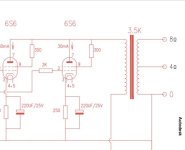
The 6e5p is biased at about 40-43mA and 240V. It needs 5V bias so a cathode resistor of 58Ω should do. For 4W output in A1, you need 4Vrms, which only with a 1:2+2 step up should do. You can get about 5W in A2 or a tad more.
: unquote
The author wants both tubes to stay in class A conducting all the time.
42 mA idle per tube means 84 mA through Rk1 which puts cathodes at +5 V.
Assuming also +5 V for Vg1 puts the grids at +1 V (as the mosfet drops about 4V) which means --5V for actual Vgk.
so +/- 4 V swing from the input transformer swing the grids up to + 5V and down to near zero limited not by input but by mosfet gnd.
Which corresponds to actual 0 V and -5 V for actual Vgk because of +5V cathode.
This way both tubes stay conducting all the time in class A as intended.
And negative voltages for mosfets are not needed.
quote:
The 6e5p is biased at about 40-43mA and 240V. It needs 5V bias so a cathode resistor of 58Ω should do. For 4W output in A1, you need 4Vrms, which only with a 1:2+2 step up should do. You can get about 5W in A2 or a tad more.
: unquote
The author wants both tubes to stay in class A conducting all the time.
42 mA idle per tube means 84 mA through Rk1 which puts cathodes at +5 V.
Assuming also +5 V for Vg1 puts the grids at +1 V (as the mosfet drops about 4V) which means --5V for actual Vgk.
so +/- 4 V swing from the input transformer swing the grids up to + 5V and down to near zero limited not by input but by mosfet gnd.
Which corresponds to actual 0 V and -5 V for actual Vgk because of +5V cathode.
This way both tubes stay conducting all the time in class A as intended.
And negative voltages for mosfets are not needed.

At second thought, you were right, negative voltage is required for the SF bottom.
Otherwise gross distortion ...
But +/- 50 V is not necessary because 6e5p / 6e6p have high gain gm=30 and mu=30.
If you look closely the schematic probably says +/- 8V for the SF1 PCB which seems to have its own PS.
Otherwise gross distortion ...
But +/- 50 V is not necessary because 6e5p / 6e6p have high gain gm=30 and mu=30.
If you look closely the schematic probably says +/- 8V for the SF1 PCB which seems to have its own PS.
Thank you so much i am now 50% understand. Need more time to read again and again to understand the rest.
The first question is step up 2X input TR. create cycle of 2VAC x 2 = +/- 4VAC
but i don't understand the calculation of 0V and 5V (as below sentence) due to +/-4 VAC from step up tr. is not VDC.
Which corresponds to actual 0 V and -5 V for actual Vgk because of +5V cathode.
The first question is step up 2X input TR. create cycle of 2VAC x 2 = +/- 4VAC
but i don't understand the calculation of 0V and 5V (as below sentence) due to +/-4 VAC from step up tr. is not VDC.
Which corresponds to actual 0 V and -5 V for actual Vgk because of +5V cathode.
Last edited:
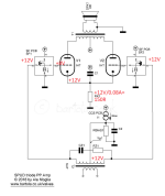
First I also thought: why the CCS go to gnd. But then I saw that the author uses a CCS into a resistor for Rbias. This creates a positive voltage at Vg1 and at the gates, allowing the CCS to return to gnd and still having enough headroom. I put some DC voltages in the drawing to exemplify (I choose 12V because this can be obtained from an A23 cell), just check how many volts the CCS needs for proper operation)
in the CCS I assume the use of enhancement mosfets, therefore 12V at the gate and circa 8V at the source.
Probably the author did this because of high capacitance of the triodes, increased by the step up of the input transformer?
in the CCS I assume the use of enhancement mosfets, therefore 12V at the gate and circa 8V at the source.
Probably the author did this because of high capacitance of the triodes, increased by the step up of the input transformer?
Attachments
Last edited:
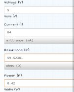
When G is at 0V, the cathode is at 5V, and indeed Rk is around 59R for 42mA. This is DC condition. For AC the grid needs to swing +-5V, this signal comes from the source follower. The source follower and the CCS needs to have the headroom that they can swing the +-5V and still have some voltage over them for proper operation. By biasing the input transformer with 12V, there will be about 8V at the source, consequently also 8V over the CCS. When AC is applied, in the valley of the sine, the source will go down to 3V (8V in DC state - 5V of applied AC), so there is now 3VDC over the CCS, which maybe is still enough for it to operate properly (a LM334 could do that).
You can also power the source follower from eg +-50VDC, one thing to note is that the 6E5P has high transconductance and that can cause runaway with too small or zero cathode resistors. So I actually like the idea of elevating the grids above 0V, this allows one to use a bigger cathode resistors which decreases the change of runaway.
For high transconductance tubes it was common to bias the grid positive and use a larger cathode resistor, see the datasheet for the D3a as an example: 10V at G1, 28mA through the 400R cathode resistor, resulting in circa 11.2V at the cathode, so effectively -1.2V bias at the grid
https://frank.pocnet.net/sheets/128/d/D3a.pdf
6J1 drive 6S6 in PSE, i will buy opt later. Thank you for your help. I got few knowledge about tube.
- Home
- Amplifiers
- Tubes / Valves
- Source follower voltage -55Vdc for 6E6P