Today received my BK 2120 and just trying make sense of the scope and also this amplifier.
This one supposedly runs unregulated yet I’m measuring the following a 1v/div using a 10x probe as that’s all I have right now.
I was expecting a square wave. Pins 11 & 14 of the 3524 are the same. Amp is running 10ohm gate resistors and 3205 fets. The amp plays otherwise.
Anything wrong here?

This one supposedly runs unregulated yet I’m measuring the following a 1v/div using a 10x probe as that’s all I have right now.
I was expecting a square wave. Pins 11 & 14 of the 3524 are the same. Amp is running 10ohm gate resistors and 3205 fets. The amp plays otherwise.
Anything wrong here?
Just a housekeeping note. The FETs and gate resistors were previously replaced, but the SG3524 is original. Also this amp was serviced by Ace Labs last.
Last edited:
Hmmm. Some upgrade then. I wonder... Now, the amp actually does work currently though I have not put it under high load yet to see what happens in the supply section...
Would it be possible to incorporate a drive circuit into this amp I wonder? It may be too much to consider however looking at other SS amps it appears it would only take a few components per leg that of which I already have. (2n2222, 2SA1562, and a .47uf cap). Not very pretty I bet. I'm after making this reliable, but if it aint broken then maybe I'm barking up the wrong tree.
Would it be possible to incorporate a drive circuit into this amp I wonder? It may be too much to consider however looking at other SS amps it appears it would only take a few components per leg that of which I already have. (2n2222, 2SA1562, and a .47uf cap). Not very pretty I bet. I'm after making this reliable, but if it aint broken then maybe I'm barking up the wrong tree.
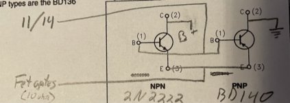
It's not difficult but may be easier with similar transistors.
For each drive pair:
The emitters are directly connected
The bases are directly connected
The collector of the NPN driver goes to B+
The collector of the PNP driver goes to ground.
For each drive pair:
The emitters are directly connected
The bases are directly connected
The collector of the NPN driver goes to B+
The collector of the PNP driver goes to ground.
Perry,
I have 2n2222-NPN and BD140-PNP. Are you saying that I could just use those two transistors only or do I need to mimic the drive circuit of say a larger Soundstream Reference amplifier; with caps and resistors etc?
This is a bit of un-charted territory for me honestly.
If all that is required are two drivers wired correctly PER SIDE, then this might be easy. However if I need to mimic exactly other SS circuits I'm probably going to get some prototype boards to do this.
Do I need the .47 cap? C71 & C72 on the 500 schematic.
Also, R154 & R161 on the SS500 are 1k, whereas on the SS300 are 150ohm R82 and R83. Change to 1ks?
Also, R154 & R161 on the SS500 are 1k, whereas on the SS300 are 150ohm R82 and R83. Change to 1ks?
The caps aren't likely necessary but if you see a problem with the drive, you may try them.
You have the 1k like the 500 and that's OK. The 150 is required because there is no PNP transistor to pull the drive back down.
You have the 1k like the 500 and that's OK. The 150 is required because there is no PNP transistor to pull the drive back down.
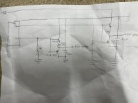
Here’s an updated draft schematic. One of these sets per side from pin 11 and pin 14.
Do you think the 10ohm gate resistors are ok here or is there a better value I should use? I need to REPLACE the 10s to fit this modification. New resistors will give me some lead room to wiggle this in.
Do you think the 10ohm gate resistors are ok here or is there a better value I should use? I need to REPLACE the 10s to fit this modification. New resistors will give me some lead room to wiggle this in.
Attachments
The 10 ohms should be OK.
Do you have the BD139?
If so, wouldn't those make this easier? I'm assuming that you are using the metal can version of the 2n2222, the 2n2222a.
Do you have the BD139?
If so, wouldn't those make this easier? I'm assuming that you are using the metal can version of the 2n2222, the 2n2222a.
I don't have any BD139. They're on my next order though. Yes I have the metal can 2n2222a that I see in most of these SS amps.
You can use the 2222a.
The value of the gate resistors is generally chosen as a happy medium. If you go really low (no resistor), the instantaneous current that the drivers see is high. If the resistor value is too high, the drive circuit can't control the FETs well enough and you'll have a condition where both banks of FETs will be on at the same time, which can cause them to run hot.
A well chosen resistor value will reduce the strain on the drivers and will control the FETs well. With 3205s in Rockford amps, I've left the original 10 ohm resistors. The 47 ohm that most people use would be a bit easier on the drivers. Anything higher than 47 ohms would be marginal with the 3205s.
Thanks. In your honest opinion, do you think me doing this modification to the drive circuit will make this amp more 'reliable' under 4-2-1 ohm high power or high current modes (IE, all modes of operation)?
Thank you
Thank you
Using the more rugged 3205 FETs will make it a bit more reliable if abused.
You can't use the 3205s without modifying the drive.
You can't use the 3205s without modifying the drive.
Back at working on this amp. I thought it was fixed and with the drive circuit upgraded, but it is not. I removed the upgraded drive transistors and the amp still suffers the same issue so I know it wasn't the upgrade that caused anything.
It plays fine when B+ is anything over about 13.5vDC. When I drop the voltage to just a few 10ths of a volt below that the amp starts to shut down with crackling audio. Below about 13.2v and the amp is silent.
I notice that regulated voltage at idle is +-15vDC, but as the music gets louder this regulated voltage drops. Rail voltage drops too the louder the music also. Its not even getting very loud and the amp is only pulling 3~5A off the bench. When I drop the input B+ voltage then regulated voltage drops as well as rail voltage.
To be honest, I think its something in the PS not driving correctly. The SG seems to not be applying full signal.
Amp is back to IRF3205 fets. 10ohm gate, 150ohm pull downs.
Any suggestions?
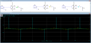
So I also get the problem with no load, with a pure sine wave from frequency generator.
What I'm doing is varying the voltage from the supply between 12-14vDC. I see good signal coming off all OpAmp outputs, R42, R43, R45, and R46.
The input leg of both driver board gets highly distorted below 13vDC from the supply. I'd say there is something wrong with the driver boards for certain, but not sure exactly what.
One thing I noticed, is this amp is currently using FEB2 driver boards whereas the 300s schematic is showing it should be using FEB1. I didn't think they were interchangeable but it does look like these boards were replaced. Do you think this is the issue?
Photos of some spare/loose/used FEB1&2 boards I have coming in a minute
Last edited:
- Home
- General Interest
- Car Audio
- Soundstream Reference 300sx