If you were referring to the 219. the LM219 is correct.
What are the part numbers on the face s of the components in red?
Are you sure that you have 1k gate resistors? That seems high.
If you don't see a designation for a component, post a good quality photo.
What are the part numbers on the face s of the components in red?
Are you sure that you have 1k gate resistors? That seems high.
If you don't see a designation for a component, post a good quality photo.
Hi Ron
I think what you are trying to do: "My only desire is to "simply?" tap into the Class D controller's analog input pin(s), to connect an external inverse feedback loop, without the phase shift of all the preceding filters. I'll eventually use them." sounds like not such a good idea to me.
There is simply so much which can go wrong with a Class d amp, and if it is not something you are really very familiar with, I would not try it.
It's intended for bass only, so I would guess it has a very low switching frequency.
Is your intention to get lower distortion? .... our ears are not very sensitive to distortion below 200Hz .....
... are you sure it does not already contain a fb loop?
If it's a fixed frequency circuit (not self oscillating) you might be able to make a loop without changing the workings much.
If it is a self oscillating circuit, you'll change the osc freq by any loop you make (fets and drivers might not like that)
As it is a mono amp I'm almost) sure by the pictures that it is an H bridge circuit, so you need to feedback loop to be balanced.
If better sound, go for something like Hypex
Sorry to be a bit negative, but having constructed class d for many years, I can testify that a lot can go boom 😀
KR Baldin
The exact circuit varies as far as feedback is designed. Some have a normal feedback loop and some have no feedback for DC compensation. The drive is AC coupled to the driver board in those amps. The diagram posted in post 7 shows the AC coupled version.
The design should be clocked and have a triangle waveform on pin 1 of the op-amp on the driver board.
The diagram shows the output configuration.
Pulling the rectifiers makes this much less risky, for troubleshooting, but I need him to find them so that they can be removed.
The design should be clocked and have a triangle waveform on pin 1 of the op-amp on the driver board.
The diagram shows the output configuration.
Pulling the rectifiers makes this much less risky, for troubleshooting, but I need him to find them so that they can be removed.
Dear Perry - Miller Effect with 1k Gate resistors would be a killer. As the schematic and physical inspection both say, they're 10 Ohms. My bad.If you were referring to the 219. the LM219 is correct.
What are the part numbers on the face s of the components in red?
Are you sure that you have 1k gate resistors? That seems high.
If you don't see a designation for a component, post a good quality photo.
I was trying to avoid removing hardware from any of the power devices. After bleeding the +/- 60V caps, they wouldn't stay discharged (dielectric absorption), faking out my $6 DMM's Diode scale. I broke down and removed the heat sink tie down of one of the RED devices. One dual diode is a fast, common Cathode MUR1620CT. The other is an unreadable common Anode from the same family.
Designators on this amp stink.
If either of you are into V/Fs or F/Vs, Linear Tech's late Jim Williams and his late buddy, my co-worker and much-revered Bob Pease, spent loads of time linearizing them. I was working and missed Jim's memorial, where Bob crashed and died on his way home to San Francisco.
When my National Semi medical group was canned, I transferred to National's Audio Group and retired the day Texas Instruments assumed management.
Baldin - it already does have overall Voltage and/or Current loops (when I find them). As far as inverse feedback loops go, I've screwed up with more than my share of unintended, highly unstable loops. I'm far too stupid to avoid them. Last year, I found the best explanation in my pristine 1952 edition of Frederick Terman's 1932 Electronic and Radio Engineering. In those days, most math wasn't written by graduate students trying to impress their thesis reviewers with ungodly complicated equations.
Sorry to have offended anyone, but it's true.
Last edited:
Removing the rectifiers makes testing less risky but if you don't want to remove them, you can test as is.
Very few of the amps like this one have bleeder resistors so you have to drain the caps yourself. They will remain charged a long time.
We're back to getting a signal at the input to the driver board. Can you see the audio signal anywhere on the amp before the driver board input pin?
Very few of the amps like this one have bleeder resistors so you have to drain the caps yourself. They will remain charged a long time.
We're back to getting a signal at the input to the driver board. Can you see the audio signal anywhere on the amp before the driver board input pin?
I'm 5 hours late getting dressed. This is far too interesting. After cleaning up and clearing my messy workbench, I'll try Ohming and bench testing the driver.Removing the rectifiers makes testing less risky but if you don't want to remove them, you can test as is.
Very few of the amps like this one have bleeder resistors so you have to drain the caps yourself. They will remain charged a long time.
We're back to getting a signal at the input to the driver board. Can you see the audio signal anywhere on the amp before the driver board input pin?
Hi Perry,Removing the rectifiers makes testing less risky but if you don't want to remove them, you can test as is.
Very few of the amps like this one have bleeder resistors so you have to drain the caps yourself. They will remain charged a long time.
We're back to getting a signal at the input to the driver board. Can you see the audio signal anywhere on the amp before the driver board input pin?
A bunch of other projects keep getting in the way. One has to do with a 1 month per year vacuum tube simulator I'd started in 1989, when the only simulations were Taylor Series expansions of triodes. I've done thousands of those tube simulations, close to 100 pages of writing and close to that many pages of math. Another is a circuit solution to a number of recent catalytic converter thefts in our community.
Now that I understand most of the little board's I/O, I'm still Ohming my way on the board. Unless I can find a schematic, I need to exhaust my Ohming efforts, before I bench test the board, by itself. I've Ohmed about 2/3 of the board, except for the 2 dual input NOR packages.
What started this whole effort - I needed the equivalent of a mult-kiloWatt, DC coupled, 12 VDC amp, because, at minimum, most consumer amplifiers, even with speaker low frequency protection disengaged, have at least 2 poles of HP coupling caps at their input. I couldn't find a low cost multi-kW 12 VDC servo amp. The consumer amp phase shift was killing me at infrasonic frequencies and I ended up with a 1 Hz oscillator. One alternative was HF chopper stabilization, using synchronous modulation/demodulation, which I hesitated to do in an audio project. I couldn't satisfactorily counter-compensate or deconvolve the phase shift. I do have a stereo DSP eval board, but hesitate to use it before understanding the 30 dB motion loop.
What took me a bit to digest - if you want to do, say, a 30 dB inverse loop down to 10 Hz, and not have gain peaking, the open loop gain can't be more than ~ 1 dB down at 10 Hz. While you can stabilize the loop, every dB of open loop gain reduction at 10 Hz, means ~ 1 dB less feedback the loop can tolerate at 1 Hz, 100 milliHz or lower, without gain peaking.
According to the Nyquist Stability Criterion, and too many others, if you want unconditional stability with a closed 30 dB loop down to 10 Hz, you have to insure there isn't 180 degrees of phase shift at any frequency below 10 Hz, where the gain is - 1. If you want to avoid gain peaking, the open loop phase shift shouldn't even be more than 145 degrees.
Ugh!
As far as I know, the input (audio) goes to the LM219 pin 4. The clock goes to the LM219 pin 5 and the output on pin 12 drives the logic ICs.
There (as far as I know) is no feedback (or any type of error correction) on that board.
As long as you have the square wave output on pins 10 and 11, the board is working perfectly.
Have you tried contacting SS for the diagram?
There (as far as I know) is no feedback (or any type of error correction) on that board.
As long as you have the square wave output on pins 10 and 11, the board is working perfectly.
Have you tried contacting SS for the diagram?
Do you mean a manufacturer will actually give you a schematic of a device in current production? Wow! I'm in process of contacting them. In the past, most manufacturers have hesitated to even sell schematics, etc.As far as I know, the input (audio) goes to the LM219 pin 4. The clock goes to the LM219 pin 5 and the output on pin 12 drives the logic ICs.
There (as far as I know) is no feedback (or any type of error correction) on that board.
As long as you have the square wave output on pins 10 and 11, the board is working perfectly.
Have you tried contacting SS for the diagram?
Thanks - I should have paid more attention. Unused pins 1, 2, 13 and 14 should have been a clue. So far, all 14 pins definitely fit the LM219. The audio input does Ohm directly to pin 4, Comparator 1's Inverting Input.
Turns out, the overall FEEDBACK loop goes back to the inverting input of main board U2C on the schematic link you'd provided. U2C's output, 2K_SIGNAL, is coupled via 10 uF, C6, to pin 1 of the driver board header. On the driver board, there's what measures 1.8k to GND at the LM219 comparator's inverting input. That's a nominal single pole 9 Hz HP filter. I can always change either the cap or resistor.
From there forward, the audio signal path may be all DC/PWM. It may or may not be easy to feed an external signal to U2C or the LM219. I'm still trying to contact SS.
I haven't been on any blogs for ages. This is too much fun. Except for the pristine, clean areas my wife bars me from, my office and lab are a shambles.
My Best,
Ron
Diagram distribution changes. Sometimes a company will send you what you need and the next month, nothing.
It's good to hear that I'm not the only person here that doesn't have a pristine bench. Mine's so bad that I've worked on a thick telephone book to elevate the amp above the mess of tools and other junk on the bench.
I was hoping that this type of repair would interest those interested in keeping old equipment alive like they do with old bakelite radios but it looks like it's just going into the sunset to die.
There are several great audio scope + FFT programs, when I'm doing AC stuff, the sound board in my laptops do everything my ancient non-memory analog scopes can't. With the FFT programs, I've taught our campus techs how to see, hear and align a garage door opener's synchronously modulated/demodulated invisible IR transmitter LED . I wonder if that qualifies as an audio thread?Diagram distribution changes. Sometimes a company will send you what you need and the next month, nothing.
It's good to hear that I'm not the only person here that doesn't have a pristine bench. Mine's so bad that I've worked on a thick telephone book to elevate the amp above the mess of tools and other junk on the bench.
I was hoping that this type of repair would interest those interested in keeping old equipment alive like they do with old bakelite radios but it looks like it's just going into the sunset to die.
My fave antique restoration was a pristine Atwater Kent, 4 stage TRF I picked up a church basement sale for $5. The only thing wrong - it was one of the first radios with a Copper oxide or Selenium rectifier field coil power supply. Replaced it with a hidden pair of Germanium power rectifiers. I miss that stinky Hydrogen Sulphide (rotten egg) odor from bad Seleniums.
Usually the dominant failures were 1) weak tubes (off to the drug store), then 2) bad (cold-to-the-touch) power resistors, then 3) bad electrolytics (hum), then 4) leaky paper caps, where wax ran out the ends.
Bakelite was a shiny, hard miracle plastic with lots of good uses, as long as you didn't drill or saw it. I remember when all we could afford was dreadful Melmac dishes. So, a few months ago I bought a pair of beautifully lacquered, nested Bento lunch boxes. Someone has rediscovered Melmac.
Have sound cards improved that much? The best I've seen had a 384kHz sampling rate.
For amp repair, I'd prefer to have a nice clean analog display. The best LCD doesn't get close to an average CRT. I have digital scopes but they were rarely used. The dithering of a digital scope where the voltage is either at ground or straight DC is beyond maddening.
Bakelite was used in a lot of older radios for the cabinets and gets mentioned a lot in those forums. Drilling may work if you use a bit like those for plastics/acrylic. It's more of a scraper than a spiral bit.
My scopes are analog with real CRTs. I can't handle 8 bit digital scopes, since they're miserable for audio. That dithering is an 8 bit A/D or D/A trying to decide in which of 256 vertical levels to paint the trace. Drives me nuts. I also hate menus. Like our so-called "smart" phones. Too many people expecting their phones to do too many things.Have sound cards improved that much? The best I've seen had a 384kHz sampling rate.
For amp repair, I'd prefer to have a nice clean analog display. The best LCD doesn't get close to an average CRT. I have digital scopes but they were rarely used. The dithering of a digital scope where the voltage is either at ground or straight DC is beyond maddening.
Bakelite was used in a lot of older radios for the cabinets and gets mentioned a lot in those forums. Drilling may work if you use a bit like those for plastics/acrylic. It's more of a scraper than a spiral bit.
I'm stuck somewhere between two knobs, one for tuning and one for the regeneration level.
Speaking of tubes - while Madman Muntz designed cheap TVs with muti-function tubes in multi-functional roles, like combined Horizontal Output and High Voltage, the tubes were run on the ragged edge. When they aged beyond the range of the Horizontal and Vertical Hold knobs, it was off to the drug store. I watched my brother-in-law clean his Crosley with a vacuum and suck up two miniature tubes.
Speaking of dither - in a DIYAudio pilot's question about his DIY ANC headset, I told him how the electronic term originated - during WW2, British techs found their bombsights were more accurate in the air than on the bench - they discovered propeller vibration was overcoming the stiction and backlash in the sights' mechanical computers and gave it the quaint British term "dither", for someone unable to make up his or her mind. The term stuck as a great way to pick up a couple of extra bits in an audio/video or measurement system. A small amount of pseudo-random dither can be applied in-band or out-of-band. Since its pattern is known, it can be subtracted out after it's done its job.
Last edited:
My scopes are analog with real CRTs. I can't handle 8 bit digital scopes, since they're miserable for audio. That dithering is an 8 bit A/D or D/A trying to decide in which of 256 vertical levels to paint the trace. Drives me nuts. I also hate menus. Like our so-called "smart" phones. Too many people expecting their phones to do too many things.
I'm stuck somewhere between two knobs, one for tuning and one for the regeneration level.
Speaking of tubes - while Madman Muntz designed cheap TVs with muti-function tubes in multi-functional roles, like combined Horizontal Output and High Voltage, the tubes were run on the ragged edge. When they aged beyond the range of the Horizontal and Vertical Hold knobs, it was off to the drug store. I watched my brother-in-law clean his Crosley with a vacuum and suck up two miniature tubes.
That's why I was amazed by my first use of a Tek scope - huge amounts of negative feedback - they didn't drift until a pot became scratchy. No Noise spray was the fix. In a bind, I've used WD-40 with equally good results.
Speaking of dither - in a DIYAudio pilot's question about his DIY ANC headset, I'd mentioned how the electronic term originated - during WW2, British techs found their bombsights were more accurate in the air than on the bench - they discovered propeller vibration was overcoming the stiction and backlash in the sights' mechanical computers and gave it the quaint British term "dither", for someone unable to make up his or her mind. The term stuck as a great way to pick up a couple of extra bits in an audio/video or measurement system. A small amount of pseudo-random dither can be applied in-band or out-of-band. Since its pattern is known, it can be subtracted out after it's done its job.
"British term "dither", for someone unable to make up his or her mind."
Like Jim Trott on the show The Vicar of Dibley.
Like Jim Trott on the show The Vicar of Dibley.
I need to get myself together and stop mixing threads.
If you recall, the driver board photo you'd sent me - the device below the dual comparator, U702 of your board - is a generic 4560 dual, low noise, high speed op op. I haven't fully Ohmed it out yet, but it's likely a combo integrator and high hysteresis, 2 level comparator used to generate both a free-running square wave clock and a highly linear triangle waveform for the upper IC's analog-to-PWM converter comparator. A real Class D driver IC could also be synch'd with the power supply's LM494 to eliminate beat notes. I know they're low level, but medical imaging systems have made me paranoid.
Remember, a small amount of design paranoia is healthy, unless and until you suffer from Analysis Paralysis.
You'da thunk a Class D driver IC could have done a better job, with a lower component count at the same or less $$. But I've never designed consumer electronics. Using jelly bean, ubiquitous parts does guarantee multiple sources and no end-of-life issues.
Last edited:
It's been off into the weeds several times but it's your thread.
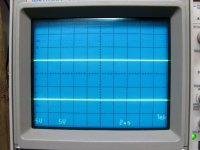
The first image is for reference to show where the traces are without input.
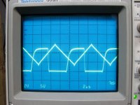
The second is the output of the 4560 and a reference I used for phase (bottom waveform).
The third image is the output of the LM219 on pin 12 (same reference on the bottom).
I prefer this type of board. Look at all of the problems techs are having getting driver ICs (IRS21844) that have little or no options for alternatives.
The first image is for reference to show where the traces are without input.
The second is the output of the 4560 and a reference I used for phase (bottom waveform).
The third image is the output of the LM219 on pin 12 (same reference on the bottom).
I prefer this type of board. Look at all of the problems techs are having getting driver ICs (IRS21844) that have little or no options for alternatives.
Attachments
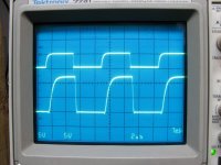
Thanks for the waveforms.
It's hard for us old geezers to keep from telling occasional war stories.
As we both know, successful manufacturers won't allow their designers to use components that don't have pin-and-function-equivalent devices.
The free-running triangle generator is a variant of a well-worn circuit.

The integrator is the pin 1, 2 and 3 half of the 4560. Apparently the SS designers felt the pin 5, 6 and 7 half, normally used as a Schmidt trigger was too slow, so they disabled that half by connecting it as a follower and grounded its + input, pin 5. Like CMOS, you never want op amp input pins floating in an undefined state.
Instead, they used the pin 7, 8, 9,10 and 11 half of the 219 as the fast Schmidt.
At the moment, I've made a confusing point-by-point wiring diagram of the those two ICs and surrounding components. I need to quickly generate a readable schematic.
I'll still try to contact SS Monday. If they won't supply a schematic, I have almost everything I need to follow my original path. I'll bench test the driver, but install beefier pins, when they arrive, before returning the driver to the amplifier. Before I do any input mods, I may want to measure how SS's FEEDBACK loop modifies the output stage gain and frequency response.
G'night
Ron
It's hard for us old geezers to keep from telling occasional war stories.
As we both know, successful manufacturers won't allow their designers to use components that don't have pin-and-function-equivalent devices.
The free-running triangle generator is a variant of a well-worn circuit.
The integrator is the pin 1, 2 and 3 half of the 4560. Apparently the SS designers felt the pin 5, 6 and 7 half, normally used as a Schmidt trigger was too slow, so they disabled that half by connecting it as a follower and grounded its + input, pin 5. Like CMOS, you never want op amp input pins floating in an undefined state.
Instead, they used the pin 7, 8, 9,10 and 11 half of the 219 as the fast Schmidt.
At the moment, I've made a confusing point-by-point wiring diagram of the those two ICs and surrounding components. I need to quickly generate a readable schematic.
I'll still try to contact SS Monday. If they won't supply a schematic, I have almost everything I need to follow my original path. I'll bench test the driver, but install beefier pins, when they arrive, before returning the driver to the amplifier. Before I do any input mods, I may want to measure how SS's FEEDBACK loop modifies the output stage gain and frequency response.
G'night
Ron
Hi Perry,Diagram distribution changes. Sometimes a company will send you what you need and the next month, nothing.
It's good to hear that I'm not the only person here that doesn't have a pristine bench. Mine's so bad that I've worked on a thick telephone book to elevate the amp above the mess of tools and other junk on the bench.
I was hoping that this type of repair would interest those interested in keeping old equipment alive like they do with old bakelite radios but it looks like it's just going into the sunset to die.
I'm unable to locate the photo of the driver board's op amp and comparator you'd sent. I've translated most of my barely workable wiring diagram into an easily-read schematic. I'd like to use your board's reference designators. Would you tell me how and where I might find it or shoot me another copy in case SS doesn't come through with at least a driver schematic tomorrow.
- Home
- General Interest
- Car Audio
- Soundstream Class D controller IC