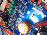
Left to right, the first 3 pins on the driver board are in, ground, mute. It's the same as the sla1500.
http://www.bcae1.com/temp/SLA1500.pdf
http://www.bcae1.com/temp/SLA1500.pdf
Ok, great, one problem solve but there are issues i think i created.
my no audio was a bad TL074 IC in the preamp circuit. After it was replaced and it was playing i think i drive it out of the chassis and with 10volts dc from the powersupply, now im getting 45volts DC across the output terminal. I removed the driver card and its gone. what could possible be wrong now? All outputs are ok and its not going on protection otherwise, even with the driver card or the output fets in place.
my no audio was a bad TL074 IC in the preamp circuit. After it was replaced and it was playing i think i drive it out of the chassis and with 10volts dc from the powersupply, now im getting 45volts DC across the output terminal. I removed the driver card and its gone. what could possible be wrong now? All outputs are ok and its not going on protection otherwise, even with the driver card or the output fets in place.
I have clean audio, I would love to confirm a few questions based on my findings (I could be wrong);
The rail volt neutral was disconnected thru the vias, the caps weren’t seeing ground neither each other. Could that cause dc on the output?
I’m getting protect and power led without the audio driver card inserted, half voltage throughout the amp but when card is in, I get solid power led, r-r oscillation and amp plays fine, does the card have a pin that triggers the power supply to full cycle?
Can I use the inline socket and bend the pins at an angle for the driver board to accommodate the cover (almost flat) and use silicone to secure it, or best I remove the socket and finalize the repair?
Attachments
If you lost the ground/reference, it could cause all sorts of problems.
Do you mean full duty cycle? If so, that's generally determined by the rail voltage. When it drops below it's target voltage, the duty cycle is increased until the voltage recovers.
Some people use sockets and it's sometimes done in amps but those OEM sockets are generally double-row with parallel connections. A pin losing its connection for even a fraction of a second (oxidation, contamination, vibration...) can cause the amp to fail catastrophically.
If the socket was installed to allow easier troubleshooting, I'd recommend using wire jumpers instead. You can have complete access to the driver board and the driver board will be functional.
Without the driver card the v- & v+ for the board is 4.5 and the rail voltage was 24v+/- after inserting the driver card the voltages for the rails 45v+/-, Is there some form of feedback pin or “sync” on the pin header (what is the 5v used for on pin 9)?
I’m going to remove the header and solder the driver board to the main amp board since it can be catastrophic. Do you have a sample of your wiring method using the jumper wires, length of wires, insulation and positioning can post here?
I’m going to remove the header and solder the driver board to the main amp board since it can be catastrophic. Do you have a sample of your wiring method using the jumper wires, length of wires, insulation and positioning can post here?
You can use Arduino breadboard jumper wires (search ebay for that). or simply use old computer ribbon cable stripped (time consuming).
5v feeds the logic IC supply pin.
I use the sla1500 diagram for most of this type amps. There is no feedback as far as I see. Sync with a 494 is very rare. That said, I've never repaired or seen the amp you're working on.
5v feeds the logic IC supply pin.
I use the sla1500 diagram for most of this type amps. There is no feedback as far as I see. Sync with a 494 is very rare. That said, I've never repaired or seen the amp you're working on.
Attachments
I’m still having some challenges with this amp. The output keeps swinging dc and I lost one set of fets on the output.
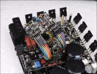
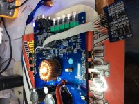
I’m at the stage now where no output install, I’ve wired up the driver board ready to take some instructions for a proper test so I can achieve the best results to have the amp running again.
I’m at the stage now where no output install, I’ve wired up the driver board ready to take some instructions for a proper test so I can achieve the best results to have the amp running again.
Attachments
I'd recommend that you remove the rectifiers and reinstall the outputs. This will allow you to test the drive circuit loaded as it would normally be.
Did you buy the FETs from a reputable distributor?
You may also want to go to a low voltage supply to test safely without much risk to the FETs. Start reading on post 64 here:
https://www.diyaudio.com/forums/car-audio/319174-4000-1-a-7.html#post5492949
Did you buy the FETs from a reputable distributor?
You may also want to go to a low voltage supply to test safely without much risk to the FETs. Start reading on post 64 here:
https://www.diyaudio.com/forums/car-audio/319174-4000-1-a-7.html#post5492949
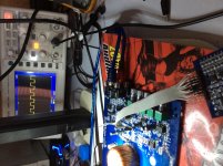
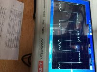
I don’t know if without the fets I would get a solid square wave, but the side that’s heating up has a waveform like my attached picture unlike the other side which is perfect square wave, the waveform is perfect up to the drive pins from the card but is distorted to the outputs.
Attachments
Can I remove just the center pins of the rectifiers or just remove them all entirely.
It’s just one set of fets was damaged, and I didn’t replace them as yet. They were the originals. How much of a lower voltage I can apply to this amp, I was currently working from a 10.1 volts 5amp adjustable bench top PS.
It’s just one set of fets was damaged, and I didn’t replace them as yet. They were the originals. How much of a lower voltage I can apply to this amp, I was currently working from a 10.1 volts 5amp adjustable bench top PS.
Yes I read the link, most of what’s describe isn’t in this amp I’m trying to repair.
(I have a tool that remove pins without damaging or weakening them)
TL072; 21844S? Those aren’t in this amp. It’s TL074 and 74HC02D
I have 12+/- already to the drive circuit when measured with the fets in the drive waves are at least alike now.
(I have a tool that remove pins without damaging or weakening them)
TL072; 21844S? Those aren’t in this amp. It’s TL074 and 74HC02D
I have 12+/- already to the drive circuit when measured with the fets in the drive waves are at least alike now.
The first thing (my suggestion) would be to remove the rectifiers and install the outputs and troubleshoot the drive circuit.
Using low voltage would be after the drive issues are resolved if you think there are other/intermittent problems that may be causing the output FETs to fail. Using low rail voltage allows you to push/pull/stress all components physically with little risk the the FETs. It's not generally necessary in these amps but since your amp randomly blew an output, it should be considered as an option.
Using low voltage would be after the drive issues are resolved if you think there are other/intermittent problems that may be causing the output FETs to fail. Using low rail voltage allows you to push/pull/stress all components physically with little risk the the FETs. It's not generally necessary in these amps but since your amp randomly blew an output, it should be considered as an option.
Ok, it’s s new morning and I’m back at the desk with this amp, I normally would forget it but all my amps of this nature has ended up as cast aside, in fact I have unfinished threads with this same design of amp that I didn’t complete.
I want to know how this work and want to get it resolve so it can educate mi for the future.
So it’s now settings; rectifiers out, output installed, amp boots from protect to power good, gain at 50% (I only have music not a set frequency) how and what are the parts or components I probe around?
I want to know how this work and want to get it resolve so it can educate mi for the future.
So it’s now settings; rectifiers out, output installed, amp boots from protect to power good, gain at 50% (I only have music not a set frequency) how and what are the parts or components I probe around?
Attachments
- Status
- This old topic is closed. If you want to reopen this topic, contact a moderator using the "Report Post" button.
- Home
- General Interest
- Car Audio
- SoundStream AR1.4500D No Audio