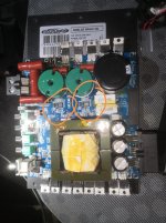
Hello! I bought this amp already broken, all fets are gone and probably something else also. There are a few chips without any markings.. Does anyone have a schematic for this amp?
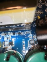
FETs have markings A6 and H3, doesn't tell anything to me. Also both power and output side controller ICs and transistor are blank. If anyone would know what these parts are for real 😀
Okay, probably found something:
Output fets marked as A6 = irfb4115 or irfb4321
Drivers are IRS20957s
And the 'gate drivers' are zxgd3005e6ta
Power side:
PWM???
Power fets marked as H3 = csd18502kcs
What would you think am I all lost here? That csd18502kcs is a bit difficult to find here, could it be replaced with irf3703 ��
Output fets marked as A6 = irfb4115 or irfb4321
Drivers are IRS20957s
And the 'gate drivers' are zxgd3005e6ta
Power side:
PWM???
Power fets marked as H3 = csd18502kcs
What would you think am I all lost here? That csd18502kcs is a bit difficult to find here, could it be replaced with irf3703 ��
I don't have specifics for the outputs but, in general, when they have 2 different FETs, the one with the higher voltage and lower current rating will go in the high-impedance model. The low-impedance will use the lower voltage, higher current FET.
The 30v PS FETs are typically only suitable for H-bridge power supplies.
Push-pull and flyback supplies need higher voltage FETs.
The FETs for a push-pull supply have to be rated for at least 2x the maximum possible 12v supply voltage.
For flyback supplies, the voltage rating must be much higher than the rail voltage.
Okay thank you Perry Babin, with a tight seeking with flashlight I probably saw those power side fets would be IRFB(x)2(x)...so maybe 428 could it be?
Should there be transistors or something like that driving the gates at PS fets? Or does the 2EDN7524G them directly is it even possible? 😀
E: I don't get how the power supply works in this kind of anplifier, seems like it's a whole different than the ones I'm used to.
E: I don't get how the power supply works in this kind of anplifier, seems like it's a whole different than the ones I'm used to.
Last edited:
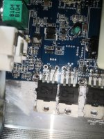
In many of the Brazillian amps, all oscillation originates at the microcontroller (I didn't see one in the photos you posted). The output of the microcontroller drives a driver IC like the 27524 which drives the FETs.
The attached diagram is similar but uses different components.
The attached diagram is similar but uses different components.
Attachments
Okay thank you again, maybe this will work some day 🙂 The 'only' part missing right now is those output gate drivers. 8pins..perhaps some half bridge drivers?
Shared album - Mika Hämäläinen - Google Photos
Shared album - Mika Hämäläinen - Google Photos
When you post photos, do so as described below. That will ensure that they will remain with the thread, even if your link no longer works.

To upload photos click the following:
Go Advanced
Manage Attachments
Browse
Upload
Repeat as necessary
Preview post to see how the post will look.
Click Submit Reply to send it to the forum.
Go Advanced
Manage Attachments
Browse
Upload
Repeat as necessary
Preview post to see how the post will look.
Click Submit Reply to send it to the forum.

That's working as it should.
I'm waiting on a few replies to emails I sent, trying to get more information on this amp.
I'm waiting on a few replies to emails I sent, trying to get more information on this amp.
- Home
- General Interest
- Car Audio
- Soundigital 3000.1d nano evo