Did the board swap exchange the LM 3915 IC as well?
If so, then start checking the small NPN transistors, Q1 - Q6.
There are also some diodes and resistors near them to check.
If so, then start checking the small NPN transistors, Q1 - Q6.
There are also some diodes and resistors near them to check.
the chips are not soldered. they press in a dip socket. both chips/lm3915 were replacedDid the board swap exchange the LM 3915 IC as well?
If so, then start checking the small NPN transistors, Q1 - Q6.
There are also some diodes and resistors near them to check.
what makes this amp difficult is that it has no numbering on the boards. really dont know where to lookOk, then check the related small parts.
Good grief, how did they ever assemble them right? Just check all the discrete transistors near the LEDs and the IC.
Are you sure that the only fault is one LED stays on?
Are you sure that the only fault is one LED stays on?
not sure but the amplifier has a dc offset 20mv on each channel. the bias is 400millivolts and it sounds very good just that darn lightGood grief, how did they ever assemble them right? Just check all the discrete transistors near the LEDs and the IC.
Are you sure that the only fault is one LED stays on?
ok, I will and report back..thanks!Trace the lit LED cathode to where it is connected. Check the parts there.
LEDs are pulled down from the positive rail by a transistor or IC to light up, by a control signal.
So either the pull-down device is shorted to ground, keeping the LED on,
or the control input to the pull-down device is bad.
Unfortunately the schematic is kind of crappy.
My guess is that a transistor Q1-Q6, diode D21-D28, or a resistor R39-R40 is bad.
See the page attached.
So either the pull-down device is shorted to ground, keeping the LED on,
or the control input to the pull-down device is bad.
Unfortunately the schematic is kind of crappy.
My guess is that a transistor Q1-Q6, diode D21-D28, or a resistor R39-R40 is bad.
See the page attached.
Attachments
Last edited:
LEDs are pulled down from the positive rail by a transistor or IC to light up, by a control signal.
So either the pull-down device is shorted to ground, keeping the LED on,
or the control input to the pull-down device is bad.
Unfortunately the schematic is kind of crappy.
My guess is that a transistor Q1-Q6, diode D21-D28, or a resistor R39-R40 is bad.
See the page at
I found R22 is connected to the cathode of the led, it shows signs of overheating but the resistance is what it shows in the diaghram
I found R22 is connected to the cathode of the led, it shows signs of overheating but the resistance is what it shows
Could you check the number of the resistor again, that can't be right.I found R22 is connected to the cathode of the led, it shows signs of overheating but the resistance is what it shows in the diaghram
R22 is not connected to any LEDs.
i think the r22 is located on the driver board,not the pwr supply board....Q7 AND Q8 ARE MPSA93 and are connected to R22 WITH...look on the driver boardquestion? is there a difference between a mpsa92 and a 93
i think the r22 is located on the driver board,not the pwr supply board....Q7 AND Q8 ARE MPSA93 and are connected to R22 WITH...look on the driver board
Attachments
i replace q7 and q8 with mpsa92The 92 has higher voltage rating than the 93, but either is ok in this circuit.
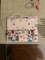
if you look on the top left side there is a cement dale resistor ...close to a small capacitor..you will see 2 pins sticking straight up....those 2 pins are connected by wires to the led
- Home
- Amplifiers
- Solid State
- Soundcraftsmen pm860 fan stuck on high speed