I have been contemplating constructing some sort of interface for my soundcard to make it more useful as a measuring instrument. One of the things I want it to do is provide isolation to avoid damage from high voltages. It also should have a differential input to avoid ground-loops.
What's the best way to go about this? An instrumentation amp with a transformer-coupled input?
What's the best way to go about this? An instrumentation amp with a transformer-coupled input?
An IA with an attenuator is a great idea, but why not just cap couple instead of using transformers? You'll compromise the CMR at 2 Hz, but that's no big deal, and no worse than transformers.
As many of us are using sound cards for measurement, a great project would be just such an interface box with switchable attenuation.
As many of us are using sound cards for measurement, a great project would be just such an interface box with switchable attenuation.
Yes, I suppose that would do. In conjunction with an IA with decent overvoltage protection it should be pretty safe. No worries about transformer distortion either.SY said:An IA with an attenuator is a great idea, but why not just cap couple instead of using transformers? You'll compromise the CMR at 2 Hz, but that's no big deal, and no worse than transformers...
I would quite like to make something useful to others, but what sort of features would people need? Currently I'm going to have the following:SY said:...As many of us are using sound cards for measurement, a great project would be just such an interface box with switchable attenuation.
- 1kHz bandpass filter on soundcard output for distortion measurements (maybe switchable to other frequencies).
- Differential input.
- BNC connectors so it can use standard 'scope probes.
- Battery powered (2x9V PP3), probably RC or RLC filtered for lowest noise.
- Switchable gain (1x, 10x).
A few things I'm not sure about:
- Anti-aliasing filter: Would this be a good idea, or can the soundcard be relied upon to do a good job of this? Maybe just an RF filter.
- Gain: Is 1x and 10x sufficient, or might there be a need for higher gain?
- Attenuation: Since it will be designed to use 'scope probes, x10 and x100 attenuation can be obtained just with the probes. Might there be a need for the circuit itself to provide attenuation?
- Is it worth transformer-coupling the soundcard output?
A 1kHz notch filter for the input might be a nice touch.
I think just an RF filter would be best. That way, a soundcard upgrade won't require a rebuild of an antialiasing filter. I don't see the advantage of a transformer on the soundcard output- the IAs will take out the common-mode noise quite efficiently. Likewise, most cards have good sensitivity, so gain is probably not needed, just attenuation.
I think you've pretty much hit my dream feature set.
I was thinking of ground loops.SY said:...I don't see the advantage of a transformer on the soundcard output- the IAs will take out the common-mode noise quite efficiently...
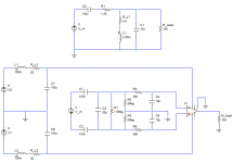
Ok, what I have so far looks like this. At the top you can see the output from the soundcard. C2 protects the output in case of 'accidents', R1/L1/C1 form a 1kHz bandpass filter.
At the bottom left, two batteries with LC filtering which should be very low noise. The inductors internal resistance is enough to damp the filter.
On the right the input. I'm not sure if this is the best way to go about setting the input impedance, but then again since this is not a very high frequency circuit it probably doesn't matter too much. The impedance seen by the probe is fairly close to 1M||20pF, but slightly lower if one end of the probe is grounded. R2/3 provide a path for the input bias current of the IA. R4/5/C4/5 filter RF.
The whole thing (except PSU) will be duplicated, for two channels in total.
Attachments
What's the coil across the output?
Do you have any thoughts on suitable IAs? The last setup I did used an AMP02, but that was because I happened to have one. There may be better devices out there to use at unity gain.
Do you have any thoughts on suitable IAs? The last setup I did used an AMP02, but that was because I happened to have one. There may be better devices out there to use at unity gain.
The coil is part of the bandpass filter: C1 and L1 resonate at 1kHz, presenting a low impedance at that frequency, forming a voltage divider with R1.
So far the most likely IA is INA128PA. It has reasonable specifications and is one of the cheapest I can find. Better ones tend to be a lot more expensive.
So far the most likely IA is INA128PA. It has reasonable specifications and is one of the cheapest I can find. Better ones tend to be a lot more expensive.
- Status
- Not open for further replies.
- Home
- General Interest
- Everything Else
- Soundcard input isolation