Have you actually looked at the output waveform on a 'scope in Balanced (TRS) and Unbalanced (TS) output modes? What is it that you are driving from the output of the soundcard?
I use a software spectrum analyzer and scope from the inputs on the same device, I always ensure that the input never clips (with the exception of a direct loop-back TRS out to XLR in which I acknowledged does clip because of the gain mismatch). I have pads for when dealing with the unbalanced inputs, and I've never had to use them because the output in unbalanced mode doesn't get close to clipping the input.
To ensure that the balanced output does not clip, I ran the TRS output through a 10/4 interfacing box and then sent the unbalanced output back to the input for verification. No clipping present, so the balanced out is just a high level out but it does not clip.
When using unbalanced, I do a loopback. I have various pads so again the input being too high is never an issue. It clips before the input.
When you connect T-S to the output jack, are you using a T-S male plug?
If so, try using a T-R-S plug, leaving R open.
If the R and S are shorted by a T-S plug, it could be causing the output amplifier to clip. Depending on the design, the board may derive the T signal by inverting the R signal.
If so, try using a T-R-S plug, leaving R open.
If the R and S are shorted by a T-S plug, it could be causing the output amplifier to clip. Depending on the design, the board may derive the T signal by inverting the R signal.
Yes I have been using a male T-S plug.
Frank, as was established earlier using only one of the outputs with ground corrects the issue. As expected, I can use either the tip or the ring as the hot for the unbalanced and it doesn't clip. So when using a T-S plug the jack shorts the Ring and Sleeve and then distorts very badly. That seems pretty bad, that it would function in that way. So whats actually clipping? And why? The final op-amp?
Frank, as was established earlier using only one of the outputs with ground corrects the issue. As expected, I can use either the tip or the ring as the hot for the unbalanced and it doesn't clip. So when using a T-S plug the jack shorts the Ring and Sleeve and then distorts very badly. That seems pretty bad, that it would function in that way. So whats actually clipping? And why? The final op-amp?
The final Opamp. It probably has something like a 47 ohm resistor in series with the R output. The same for the T output.
When connected to S, this causes the R output to operate into a 47 ohm load .... too low for the chip. Leave the R open or connect it to S using a resistor which matches the impedance that the T sees.
I've seen this on other pieces of equipment. It puzzled me too until I figured out what was happening.
Let me see if I can figure out the parts, I'll open it up and see whats actually there. Any difference in performance by lifting the ring and not using it shorted ( i mean if I corrected the issue)?
That would be my choice. The output Opamps won't have to work so hard.
The distortion will be lower if you don't load the unused R.
Please let us know what you find.
Glad to give you my two-cents worth.
The distortion will be lower if you don't load the unused R.
Please let us know what you find.
Glad to give you my two-cents worth.
I'm presently listening to it with manually jumping to the posts (so it doesn't bridge the ring and sleeve) will full digital volume and it sounds pretty good, less distortion in the mids and the dynamics seem a lot stronger than before. Would still love to know exactly whats happening though, and certainly why they would design it this way :/
OK, it seems you have already got to the bottom of the issue as regards how the volume control is implemented. Thinking in terms of 16-bit signed data for example (16-bit .WAVs are signed) the maximum excursions are -32768 and 32767. 0.5dB (the gain/attn step offered by the DAC) is a factor of 1.0592537251772888788092803732781. 32768 reduced by 0.5dB is 30935 (rounded). To reduce the output by 0.5dB the input sample would be multiplied by 30935 and divided by 32768. The division is trivial as it simply consists of discarding the rightmost 15 bits. Greater reductions in volume simply require a smaller multiplier.
Since the wheel-operated volume control can be overridden in software, it is obviously being read (it could be an encoder or a pot being read by an A/D) and the control effected by commanding the DAC. Personally, I would never design a DAC that worked like that precisely because of the degradation of S/N and quantization noise, which means that a user requiring the best performance from the DAC should never use the volume control, or rather should always have the volume set to max. It's not uncommon though in 'consumer' applications to disregard considerations of absolute quality in favour of 'convenience'.
As regards the output opamps the datasheet recommends an output filter using at least one opamp. This filter has a single-ended output. To convert this to balanced a couple more opamps would typically be employed:

This means we have 3 opamps per channel. The designers probably used the remaining one for a final adjustment of gain preceeding the balanced line driver.
w
Since the wheel-operated volume control can be overridden in software, it is obviously being read (it could be an encoder or a pot being read by an A/D) and the control effected by commanding the DAC. Personally, I would never design a DAC that worked like that precisely because of the degradation of S/N and quantization noise, which means that a user requiring the best performance from the DAC should never use the volume control, or rather should always have the volume set to max. It's not uncommon though in 'consumer' applications to disregard considerations of absolute quality in favour of 'convenience'.
As regards the output opamps the datasheet recommends an output filter using at least one opamp. This filter has a single-ended output. To convert this to balanced a couple more opamps would typically be employed:
This means we have 3 opamps per channel. The designers probably used the remaining one for a final adjustment of gain preceeding the balanced line driver.
w
Last edited:
Yeah that was what I was fearing, totally stupid process. The reason they did it that way, obviously, was that it was far easier to encode a single pot once and use that value for all of the output channels (there are 8 analog outs) than to have a way to control them all afterwards. A single pot for digital versus 8 analog TRS pots, or whatever other scheme.OK, it seems you have already got to the bottom of the issue as regards how the volume control is implemented. Thinking in terms of 16-bit signed data for example (16-bit .WAVs are signed) the maximum excursions are -32768 and 32767. 0.5dB (the gain/attn step offered by the DAC) is a factor of 1.0592537251772888788092803732781. 32768 reduced by 0.5dB is 34710 (rounded). To reduce the output by 0.5dB the input sample would be multiplied by 34710 and divided by 32768. The division is trivial as it simply consists of discarding the rightmost 15 bits. Greater reductions in volume simply require a smaller multiplier.
Since the wheel-operated volume control can be overridden in software, it is obviously being read (it could be an encoder or a pot being read by an A/D) and the control effected by commanding the DAC. Personally, I would never design a DAC that worked like that precisely because of the degradation of S/N and quantization noise, which means that a user requiring the best performance from the DAC should never use the volume control, or rather should always have the volume set to max. It's not uncommon though in 'consumer' applications to disregard considerations of absolute quality in favour of 'convenience'.

So they take the differential output from the dac, convert it to single ended with one half of one of those dual channel opamps, and then convert it back to differential with another opamp? Isn't that a sort of stupid way to do it?As regards the output opamps the datasheet recommends an output filter using at least one opamp. This filter has a single-ended output. To convert this to balanced a couple more opamps would typically be employed:

I see, so since I'm not concerned with balanced output perhaps I can bypass the final balanced line driver portion and jump directly to the output pin of that first opamp. Does that make sense?This means we have 3 opamps per channel. The designers probably used the remaining one for a final adjustment of gain preceeding the balanced line driver.
w
The opamp datasheet is http://semicon.njr.co.jp/njr/hp/fileDownloadMedia.do?_mediaId=5679
for reference.
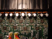
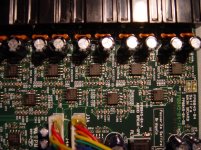
Pin 1 on it, the top left most pin in the picture, is the output for the first opamp. I am guessing that this would be the point to attach to right?
Thanks again for all of the assistance guys, glad we have figured out a lot of it 😀
So they take the differential output from the dac, convert it to single ended with one half of one of those dual channel opamps, and then convert it back to differential with another opamp? Isn't that a sort of stupid way to do it?
Stupid? I don't necessarily want to comment on that, but here's the diagram from the datasheet:

I see, so since I'm not concerned with balanced output perhaps I can bypass the final balanced line driver portion and jump directly to the output pin of that first opamp. Does that make sense?
Pin 1 on it, the top left most pin in the picture, is the output for the first opamp. I am guessing that this would be the point to attach to right?
I don't see anything wrong with your reasoning, but messing around in there making connections, there's always the chance that you'll do some damage. There's the gain consideration too, just so you don't end up with insufficient drive voltage.
Good luck.
w
Yeah I'm not sure it would be worth it either, though at present I'll likely have to make an attenuator as the output is pretty high.
And sorry bringing "stupid" into the discussion, it is a working and successful product and I don't want to knock them for it 🙂. To the relative layperson it seems a strange implementation but there are many considerations, like cost and difference in performance, that they were aware of and I'm clearly not so it was a little judgmental on my part.
The next step will be to try to latch on to the output leg and hope that the output level will be about what I'm looking for. If that fails, I'll have to start a new inquiry into building a quick pad.
Thanks again to all who contributed in the thread, you have been extremely helpful and understanding 😎
- Status
- Not open for further replies.
- Home
- Source & Line
- Digital Line Level
- Soundcard clipping when volume control set to full