hey there,
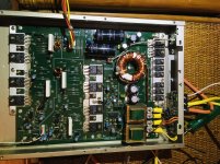
picked up a Sony XM-10020 on a hunch that it was possibly not working and unfortunately I was right. Had luck fixing another amp recently so giving it another go. Having fun so far looking through the service manual and BCAE and learning a little as I go. Thank for the help
Using a 12v power supply the center leg of the supply FET's is 12.0v. The Rectifier Diode (D305, D306) on the outside legs all have 5.8Vdc. The center leg on D305 has 25.9Vdc, and the D306 has 37.8Vdc. The voltages I am reading are the positive B+ and negative B- rail voltages? Which should be +-40 respectively? I am not sure where to go next, are the rectifier diodes bad?
The data for the values on the IC302 (uPC494C) is way different than the measurements I took.
mine
Pin 1: 0.0
Pin 2: 0.5
Pin 3: 5.0
Pin 4: 5.0
Pin 5: 11.7
Pin 6: 11.7
Pin 7: 4.1
Pin 8: 4.1
Pin 9: 11.2
Pin 10: 0.0
Pin 11: 3.7
Pin 12: 1.7
Pin 13: 0.8
Pin 14: 0.1
Pin 15: 0.5
Pin 16: 0.0
manual
Pin 1: 0
Pin 2: 0.4
Pin 3: 0.1
Pin 4: 0.8
Pin 5: 1.6
Pin 6: 3.7
Pin 7:
Pin 8: 14.4
Pin 9: 4.9
Pin 10: 4.9
Pin 11: 14.4
Pin 12: 14.4
Pin 13:
Pin 14: 5
Pin 15: 0.4
Pin 16: 0
Attachments
You have the pin numbering wrong. Repost with the right configuration.
You need to measure secondary voltages with the black probe on the secondary ground (one of the non-bridging speaker terminals).
You need to measure secondary voltages with the black probe on the secondary ground (one of the non-bridging speaker terminals).
That's much better, went off the schematic drawing for the pin out. The IC is clearly numbered on the board but I did not catch it, thanks again for the help
OK, on the rectifier diodes center legs secondary voltage are both 30.1Vdc, the outer legs all are 0.0Vdc
Pin 1: 0.0
Pin 2: 0.5
Pin 3: 0.1
Pin 4: 0.8
Pin 5: 1.7
Pin 6: 3.7
Pin 7: 0.0
Pin 8: 11.2
Pin 9: 4.1
Pin 10: 4.1
Pin 11: 11.7
Pin 12: 11.7
Pin 13: 5.0
Pin 14: 5.0
Pin 15: 0.5
Pin 16: 0.0
OK, on the rectifier diodes center legs secondary voltage are both 30.1Vdc, the outer legs all are 0.0Vdc
Pin 1: 0.0
Pin 2: 0.5
Pin 3: 0.1
Pin 4: 0.8
Pin 5: 1.7
Pin 6: 3.7
Pin 7: 0.0
Pin 8: 11.2
Pin 9: 4.1
Pin 10: 4.1
Pin 11: 11.7
Pin 12: 11.7
Pin 13: 5.0
Pin 14: 5.0
Pin 15: 0.5
Pin 16: 0.0
Red probe on center leg of d305, d306 rectifier diodes black prope on negative speaker terminal not bridged
I don't think there is a problem with the rail voltage. The 12v input to the amp seems to be lower than the 14.4 used in the service manual.
thanks, this is where I ended up tonight , checking output transistors
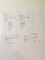
When checking transistors (bipolar or FET) with your meter set to ohms, you should not read anything near 0 ohms when the probes are touched to the terminals of any individual transistor in any configuration. If any are shorted (~0 ohms between any 2 legs of any individual transistor), they will likely be shorted from leg 2 to leg 3 but you should check 1-2, 1-3 and 2-3.
the smaller transistors 2SA1358 and 2SC3421 all legs any combo have readings greater than 0 and no O.L which all should be good?
the larger transistors (2SA1671, 2sc4386) which part numbers have them labeled as bipolar transistors in google search don't test out the same way. Across the first two legs, the meter in ohms reads O.L, and the probe config is reversed on the different resistor models. Not sure how to say it so I drew a picture to illustrate.
I need you to find why your meter was reading positive on both rectifiers. That should not be possible and could cause problems later. If you read across the B+ and ground on your amp with the proper polarity, you should read approximately +12v but when you reverse the probes, you should read negative voltage. Do you read negative voltage or does you meter still read positive voltage?
I doubt that there is a problem with the output transistors (without looking at what you posted when checking them). When the output transistors fail, they typically short causing the amp to shut down.
I doubt that there is a problem with the output transistors (without looking at what you posted when checking them). When the output transistors fail, they typically short causing the amp to shut down.
Once again, sir, you are a genius and me, not so much. I stand corrected the D306 rectifier is indeed negative voltage while the other is positive.
so if rail voltage is good, and output transistors most likely ok, I should the check then check input board?
thanks for your time
so if rail voltage is good, and output transistors most likely ok, I should the check then check input board?
thanks for your time
Do you have either positive or negative rail voltage on the center legs of all outputs and 1v or less on all of the rest of the legs?
Have you tried adjusting the gain with a signal source connected to see if audio ever played through?
Did you use a signal source with a grounded shield or did you use something like a cellphone?
Have you tried adjusting the gain with a signal source connected to see if audio ever played through?
Did you use a signal source with a grounded shield or did you use something like a cellphone?
D208, D108 part 2sc3421, DO NOT have +-30Vdc, the voltages across the legs from left to right are -1.2, +1.2, -0.6 on both transistors.
All the other output transistors test out as described.
I use a JVC head unit with a cheap RCA for the source. I can make an RCA with a grounded shield if that will be beneficial, only ground one side correct?
When I turned up the gain the very little output I had disappeared. I was just messing with the input board, supposed to have +15vdc and -15vdc, I didn't write down the readings but the positive was close. The negative was about half of the positive and when I turned up the gain the negative voltage dropped to around -1.2vdc. I did notice an IC301-2 on the input board which looks pretty rough. Going after the schematic to see if I can find the voltages
Is the head unit being powered from the 12v supply as the amp?
What is the resistance from the RCA shield on the head unit to the ground terminal of the amp?
On Q113, 114, what is the DC voltage on their center legs? (black probe on non-bridging speaker terminal)
What is the resistance from the RCA shield on the head unit to the ground terminal of the amp?
On Q113, 114, what is the DC voltage on their center legs? (black probe on non-bridging speaker terminal)
yes same power supply
resistance right shield RCA head unit to right ground terminal on amp is 0.3
resistance on left fluctuate and climbed from 40 to 180 and kept going bounce to 300 then down to 180 and climb
Q113 -0.5, -30.2, 0.0(+0.1)
Q114 +0.6, +32.9, 0.0(+0.1)
check this out IC301-2
Pin 1: +13.3
Pin 2: +7.8
Pin 3: +7.8
Pin 4: +8.5
Pin 5: +7.5
Pin 6:+7.6
Pin 7:+13.3
Pin 8: +14.2
voltages on the schematic are
Pin 1: 0.0
Pin 2: 0.0
Pin 3: 0.0
Pin 4: -14.5
Pin 5: 0.0
Pin 6: 0.0
Pin 7: 0.0
Pin 8: +14.5
The left shield is defective. You should read very near 0 ohms from the RCA shield to ground.
I didn't mention but these needed to be measure without being plugged into the amp.
Post the DC voltage on all terminals of Q301 and 302.
I didn't mention but these needed to be measure without being plugged into the amp.
Post the DC voltage on all terminals of Q301 and 302.
- Home
- General Interest
- Car Audio
- Sony XM-10020 repair