Here are my right and left channels.
My VFETs were not the best matches.
The front end outputs were at about .01% distortion with no global feedback at 2.8 Vrms. No third harmonic. Offset minimum.
I haven't had a chance to adjust the cascode feedback resistors, but I will.
I have been trying 2.3K and 4.75K and no feedback
What was your Gain measurements?
BDP thanks for sharing.
I fed 0.199VAC 400hz signal and measured 1.64VAC output into no load ie 18.3db and into a 4r load I got 1.55VAC ie 17.8db gain
Have you tried increasing your output bias above 1amp since your H2 is high? Try 1.5amp and see whether H2 drops like in my experience.nash
1amp bias is enough for these heat sinks.
Have you listened open loop, no feedback?
Simple material is very good, voices, horns, piano. The bass is not as tight and controlled, but on my full range drivers it's not bad. Maybe a good trade off for the voicing. It's on the other end of the spectrum of your earlier listening experience .
To open the feedback just remove the jumper provide on AL boards (maybe you have installed a switch) bias stays the same, gain goes up.
Try it and let us know what you think!
1amp bias is enough for these heat sinks.
Have you listened open loop, no feedback?
Simple material is very good, voices, horns, piano. The bass is not as tight and controlled, but on my full range drivers it's not bad. Maybe a good trade off for the voicing. It's on the other end of the spectrum of your earlier listening experience .
To open the feedback just remove the jumper provide on AL boards (maybe you have installed a switch) bias stays the same, gain goes up.
Try it and let us know what you think!
No I have not listened open loop but ready to try.
But there is no R46 resistor to G like in Nelson's original schematic. Will this not matter ?
nash

No I have not listened open loop but ready to try.
But there is no R46 resistor to G like in Nelson's original schematic. Will this not matter ?
nash
Just remove the jumper labeled 'SW'. The gain will go up. No adverse effects opening or closing the feedback loop.
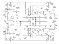
Having sat on my partly assembled Vfet boards for quite a while I finally plucked up the courage to connect them to the power supply. Would someone please confirm that my voltages are good for me to continue with the biasing. Particularly concerned with the g-t18 reading of close to 16V.
.jpg")
.jpg")
.jpg")
Hi Marra,
I suspect your G-T18 reading is mostly coming from T6-T7 and T8-T9 being different. Are P3 and P4 fully counterclockwise? It looks like you are using
Toshiba mosfets and perhaps a combination of low Vgs and high Idss of the jfets
mean they are already on and conducting.
If you increase P4 slightly so that T8-T9 increases closer to the 0.124 T6-T7 then
the G-T18 voltage should drop.
Dennis
BDP have you had any success changing the harmonics; you had posted about it on March 31.
nash
I put a 250 K pot. in parallel with the cascode feedback resistor, 22K and adjusted watching the distortion and harmonics. The front end distortion went down, very small change, but the harmonic ratios didn't change at the output.
The majority of the harmonic structure comes from the output section. The next step is to try and adjust the voltage regulator in the output stage and see if the harmonic ratios change. I have no clue which regulator to try first.
I tried a 200k, a 100k and finally a 47k in parallel with R29 and looked at hamonics and distortion at output. About a 1.5db rise in H2 with the 100k and about a 3db rise in H2 (meaning the spike was higher on Arta) with the 47k over the H3 which seemed to stay the same. So in my case the ratios did change. Distortion predictably increased at each step. With the 47K in place I balanced the front end output and then increased the output bias and the H2 came down and matching the H2/H3 ratio to what it was before the paralleling I arrived at the same distortion level. So I figured I achieved nothing in the process. I forgot to measure whether the overall system gain stayed the same.
That sounds good. You can proceed with biasing up the front end.
Cheers,
Dennis
Thanks Dennis. I am happy to say that everything went well and the one channel plays music. Now for channel 2 and then I guess it will need re biasing after things are cased up.
Not really - there is still a lot of Vds variation with signal. The original intent was
to shield the VFETs against rail noise and provide low turn-on currents. The small AC
modulation that you do see is to maximize the peak swing.
However, it points out an opportunity to trim the AC voltage experienced by the
VFETs against the load values.
to shield the VFETs against rail noise and provide low turn-on currents. The small AC
modulation that you do see is to maximize the peak swing.
However, it points out an opportunity to trim the AC voltage experienced by the
VFETs against the load values.
Thank You Mr. Pass!
Hope for more interesting Papa topology Vfet's tricks in Part 3.
Something to learn again 🙂 Kind regards
Hope for more interesting Papa topology Vfet's tricks in Part 3.
Something to learn again 🙂 Kind regards


- Home
- Amplifiers
- Pass Labs
- Sony vFET Amplifier Part 2