If you can rotate each jfet 90º ccw it would be easier to tie them with a zip tie for better thermal coupling. Or will you be using some sort of heatsink?
Yeah, the Type 0 EVUL Heatsink will work here, provided the BJTs fit (need to verify 2sa970/2sc2240). Probably can use other JFETs too as cascode, I would think.
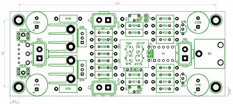
Here's where I am at with the combo output stage:
...just a small question luvdunhill,
- Different values for source resistors on output is your effort for tighter matching ?
Carlos
Last edited:
...just two small questions luvdunhill,
1- Different values for source resistors on output is your effort for tighter matching ?
2 - How long is main board ?....i am halfway to building a chassis and was counting on two pairs a side so now i am hopping this still fits.
Carlos
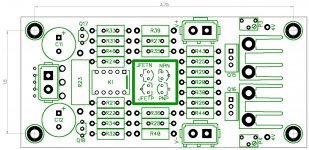
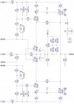
I am allowing for source resistors, they aren't present on the official VFET2 schematic. They will need to be jumpered with a bit of wire if not used. The article says they aren't needed and the lack causes some nice benefits, but with the extra device (3 deep) it seemed wise. I am open to removing them, but definitely wanted a prototype board to have the option.
All my posts should have dimensions on them - the width is on this very page.
Finally getting this project off the ground. Thanks to Botte and Flocchini for their help in building this project, and La Ode for the board layout.
Here is a video link to the working prototype.
Some production boards will need to be respun to add a wire to the output board and to eliminate the TO-220 bipolar in the front end, also to use wider spacing for TO-92 TL431.
https://youtu.be/kWSlbYg01pQ
Also viewable/listenable on instagram @emojiviasound
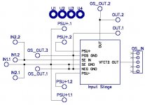
Here's the VFET2 Front End. I'm trying a different board house for this than the output stage (PCB Way versus Elecrow). Just put the order in for the front-end and the output stage already shipped from PCB Way.
Attachments

What is happening regarding this project.
Is Nelson providing pcbs for the diyaudio store or is it up to us to do our own pcb?
Is Nelson providing pcbs for the diyaudio store or is it up to us to do our own pcb?
I will finish the pcb when the bracket is in my hands.
😎


Here is a video link to the working prototype.
https://youtu.be/kWSlbYg01pQ
Also viewable/listenable on instagram @emojiviasound
Congrats Tea-Bag.
Was there a heatsink attached to the bracket? (Maybe I missed it.)
How large/thick is that bracket you used?
Cheers,
Dennis
Congrats Tea-Bag.
Was there a heatsink attached to the bracket? (Maybe I missed it.)
How large/thick is that bracket you used?
Cheers,
Dennis
HI Dennis, Not attached yet to a larger heatsink. Its thick enough to run at a low bias for 30 minutes or so.
I believe Botte set me up with getting this bracket from the US. (I cant seem to find resource) It is a very thick bracket, that the PINS barely make it to the PCB. Something a little thinner I think would work well once attached to the heatsink. I will set up a seperate thread for the board soon.
I would not take this on without a half-decent drill press. A cordless one, unless your gifted is not going to make anything line up right. All the holes are drilled with plenty of space around them, and then covered a little teflon sleeve covers the pins where possible.
I would not call this a novice project at all, unfortunately.
I used a piece of 2 inch "L" of .25 inch thick 6061 T6 aluminum. It's a pretty common profile, most hardware stores in have it.
I used 1.5 x1.5 L T6061 but I would follow Botte's recommendation of 2 x 2 - More surface area to heatsink
Best
Bob
Best
Bob
Vfet kits, pcbs in near future are in DiyAudio Store
I'm thinking they might be offered on Valentine's Day because Papa loves us so much! 😀
Attached is the bracket I had made, and which I am using to revise the board.
It has been provided to DIYAudio for the purpose of the kit, and they are in
charge of having them made.
I expect to have working units in the Store chassis around the end of Feb.
😎
It has been provided to DIYAudio for the purpose of the kit, and they are in
charge of having them made.
I expect to have working units in the Store chassis around the end of Feb.
😎
Attachments
Attached is the bracket I had made, and which I am using to revise the board.
It has been provided to DIYAudio for the purpose of the kit, and they are in
charge of having them made.
I expect to have working units in the Store chassis around the end of Feb.
😎
Thanks Mr Pass for last kit update informations.
Great i have complete all front end components and vfets so
i stay in tune for other news about final simplified one pair mono Vfet2 amplifier version.
Could DiyAudio Store sell official pcb's only ?
This option give more chances afford some as well for diyers without vfets on bench.
Kind regards

I'm thinking they might be offered on Valentine's Day because Papa loves us so much! 😀


- Home
- Amplifiers
- Pass Labs
- Sony vFET Amplifier Part 2