
My VFET P2 with:
+ JBL LE 15A double bass
+ JBL 375 mid
+ Fostex T500A tweeter
+ CEC TL 2X MKII CD transport
+ Weiss 202 D/A (volume out)
+ Without preamp
The result: the sound is... excellence

+ JBL LE 15A double bass
+ JBL 375 mid
+ Fostex T500A tweeter
+ CEC TL 2X MKII CD transport
+ Weiss 202 D/A (volume out)
+ Without preamp
The result: the sound is... excellence
nagini ....... that's some serious setup
I'm so glad to see it ..... and that you're satisfied
😉
I'm so glad to see it ..... and that you're satisfied
😉
More some images...
Matching VFET


PCB ready

Mount parts


Adjust front-end (bias/offset)


Mount VFETs and fan on the heatsink


If this is your hobby you are either extremely rich or extremely addicted. 😀
Very nice.
what drivers are you using in those big horns? Also, we now know where all the vfets disappeared to🙂
...we now know where all the vfets disappeared to🙂
10 pairs and 6 Nch singles also landed in Italy one year ago 😛
Just ordered other 6 Pch untill they last 😉
guilty as charged! stole all the vfets we don't have any left to play with!10 pairs and 6 Nch singles also landed in Italy one year ago 😛
Just ordered other 6 Pch untill they last 😉
I bought 8 pairs at circuitdiy before VFET P2 released. After VFET P2 released, I bought more 4 pairs. Total 12 pairs I bought for me and for some my friends.
2SJ28 still in stock now; so I think in the future, I have a plan to buy 4 pairs J28 and build a VFET circlotron hybrid amp (input => volume => tube => OPT => VFET circlotron), the tube I will use 26 (DHT) or C3g pentode, I hope it's fine
In the picture, just VFET P2 power amp is mine, others in the system is my friend's. Bass JBL LE15A and horn JBL 375 are 16 ohm type, just Fostex is 8 ohm😎
I am working on a PCB and was wondering if anyone could measure the pins of a few of the Sony VFETs (both polarity, both pins) as I am looking for a flush mount PCB receptical to use and don't have he devices with me. It would be super helpful. Thanks!
Are you wanting to know the pin thickness? .040, is what my caliper reads, Spacing is standard, Mine measured .422.
Last edited:
Are you wanting to know the pin thickness? .040, is what my caliper reads, Spacing is standard, Mine measured .422.
Yes, perhaps the length also. What does the .422 refer to?
The IRF240 / IRF9240 parts have a data sheet with a drawing and they show a diameter range of .058-.063. They are a TO-204AE though, which is a modified TO-3 (not sure what exactly is modified, perhaps lower profile "can"?)
http://www.irf.com/product-info/datasheets/data/irf240.pdf
I am looking to use "gage jacks" per the recommendation here: (probably a Mill-Max equivalent to the Cambion part mentioned in the article). Hence need to find the pin diameters within a pretty close margin 🙂
http://www.ti.com/lit/an/sboa020/sboa020.pdf
I didn't do as good of a job as Tea-Bag and Co. making a nice mating system between the OS and the IS. I brought everything to 5 pins and then three jumpers needed to select between either the CSX2 or VFET2 style OS. But at the five pin header, I couldn't get a nice way to mount the daughter board (I am a sucker for elegant solutions). I will post my progress a little later today 🙂
Sorry, thousandths of an inch.
The overall length of the package is 1.535 thousandths
Thanks! What about the length of the pin itself?
Thanks! What about the length of the pin itself?
The length of the pins are 470 thousandths
Here's where I am at with the combo output stage:
Whats the length of the PCB output board?
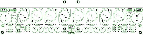
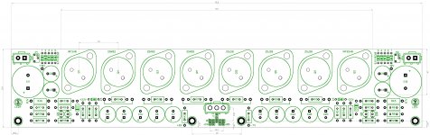
The keep-out area where the flange will be is 9.5" wide (where the TO-3 are mounted). The overall width is 12.5". I'm planning on using the Conrad MF35-151.5.
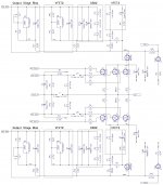
ok, I just ordered 5 prototype boards. I ended up with the following dimensions. The annular ring around the output connector and the VFETs are small because they are actually sockets that will be affixed into the holes. I chose the VFET spacing by looking at a number of different insulators and choosing a distance that would work with most. The outer pads you see around the gate resistors are actually source resistors and need to be jumpered if not used. This way seemed to conserve board space the most and allow for some flexibility.
So, off to work on the input boards. I'm thinking I'll either allow them to be mounted on the actual I/O connectors (then a cable to the OS boards), which would also include PCB mount connectors or via the pads shown via some sort of board-to-board mounting system, which I've already scoped out from Mill-Max.
Let the fun begin!
Attachments
Is it okay to use two properly rated zener diodes to create a voltage for a relay coil off the + and - rails (nothing would touch ground, the coil "between" the two zeners)? I would use a good small-signal relay in the FE, to replace the feedback switch in the schematic.
Last edited:
- Home
- Amplifiers
- Pass Labs
- Sony vFET Amplifier Part 2