Bones
I believe C4 is under Q6 - the 1 and the 4 are very similar in appearance but are different the one has a base whereas the four doesn't
Best
Bob
I see the difference now, sorry.
Balanced input would be on my wish list too, not a requirement though.
Thanks for your work to date.🙂
I was thinking that if I don't have sufficient matched pairs I would build 4 boards with a single set of VFETS and set up in mono balanced mode ( see F4 manual )
Essentially one board is used for pos phase and one board for neg phase per stereo channel.
Just a thought.
Bones13 - no reason to be sorry - I have looking at images with my magnifying glass 😀
Essentially one board is used for pos phase and one board for neg phase per stereo channel.
Just a thought.
Bones13 - no reason to be sorry - I have looking at images with my magnifying glass 😀
Rev2 the Nelson mods
I installed the new minor value changes Nelson, so graciously, gave us.
It's more similar to the csx1 now. The changes increased the gain to 18 dB. It opened up the sound and keeps better control of the bass than the original with no global feedback. I like it better than the original 🙂
I will have an informal shootouts with the csx1 this weekend and report back what the golden ears say...
Gracias. 😎
Hey Mr Pass you are learning Spanish, you are the guy of today.
We invited you to some party-Burning-session in the Mediterranean cost.
We are on Europe and I guess a lot of the guys from the cost and other can come and make "The big meeting Diy on the beach"
Germany is a two hours with direct travel, English people have directly fly’s to Mahón, Our capital.
We invited you to some party-Burning-session in the Mediterranean cost.
We are on Europe and I guess a lot of the guys from the cost and other can come and make "The big meeting Diy on the beach"
Germany is a two hours with direct travel, English people have directly fly’s to Mahón, Our capital.
Last edited:
It is possible to implement footprints for P1 to P4 Bourns 3296Y and 3296W.
Walter
Yes
I doubt he is still learning it. Para nosotros que vivimos en California, hablar español es una necesidad.
🙂
🙂
Hey Mr Pass you are learning Spanish, you are the guy of today.
We invited you to some party-Burning-session in the Mediterranean cost.
We are on Europe and I guess a lot of the guys from the cost and other can come and make "The big meeting Diy on the beach"
Germany is a two hours with direct travel, English people have directly fly’s to Mahón, Our capital.
Of course he is learning Spanish. After all, he lives in CaliMexico which is now a Spanish state, and Spanish will soon be the official language.
This is way over my head 😀
First I didn't know what ZM meant at all with cascoding the SIT's properly. After reading the article again and Antoinel his comments, I understand that the IRF's cascode the SIT's.
I think I understand a little bit what R17, C7 and R18, C8 are doing, but it stops here for me.
Why ZM suggest to take the modulation from Q15 and Q16 sources?
Is it because Q15 and Q16 than become common drain and the OS is common source, so the whole amp is not inverting anymore? Or do you mean something totally different ?
Sometimes explanations on DIYAudio are given in a short sentence, special code, which are difficult to decipher 😱 for me...
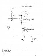
Hello WalterW. I hope the simplified and attached schematic helps with the questions above. Please note the following:
1. This schematic shows only the circuit for the positive side of the power output stage to minimize complexity.
2. N-channel Mosfet Q1 is part of the positive voltage regulator which fixes a stiff voltage of +19Vdc at the source terminal of the 2SJ28.
3. The voltage to the gate of SIT is at +27Vdc; which allows a drain current for SIT say [for example] of 1Adc.
4. The voltage difference between that of the gate and the source of SIT is the important variable.
5. This voltage difference between source and gate of SIT is modulated by the AC input signal Vin [see caricature]
6. As shown, as the AC input signal goes lower than +27 V, the SIT conducts more.
7. Lets talk about the P-channel Mosfet Q2 which is the "cascode" device for SIT.
8. The voltages at the three terminals of Q2 are realistic.
9 Vds for SIT is thus held ~constant at 5Vdc. As this SIT processes the input signal, the current through it moves up and down from the idle value of 1 Adc.
10. Thus the dynamic impedance of SIT is changing appropriately
11. SIT is like a dynamic resistor in the source of Q2; which modulates the impedance of Q2 and thus allows this variable current to pass through to the load Zl.
12. The drain voltage drain of SIT is fixed at +14Vdc, and the drain voltage of Q2 tracks the power output signal which is phase inverted.
13. Q2 needs to stay in "active cascode" mode by keeping a certain minimum Vds across it; say 5Vdc.
14. So the peak positive signal can/may only reach a maximum of +9Vp; versus +14Vp absent cascoding; thus leading to an attenuation of available power output.
15. SIT is a voltage variable resistor [meaning triode-like] while Q2 Mosfet is a voltage variable current source [pentode-like]. Both devices are connected in series like two resistors in series.
16. So, is the character of the resultant current flowing though both of them to the load "triode-like"; a default from SIT or pentode-like from only Q2 or some combo? It is clear that the DIYer is exclusively interested in triode-like performance and not a pentode-like performance.
I believe that you have an understanding of the modulation change which Zen Mod spoke of by using the source of the signals to the SITs from the source terminals of the Front End Mosfets. In addition, one may use the so-called LSK preamp from BA 2013 instead [inverts phase]; but one looses the benefit of cascode feedback in the front end of Al or is it Betty?
I hope this helped.
Best regards.
i
Attachments
Esteban, are you still planning to attend BAF?
Probably I will.
I see the difference now, sorry.
Balanced input would be on my wish list too, not a requirement though.
Thanks for your work to date.🙂
my primary source is ntd1, so I pretty much require it lest I relegate that to the garage or something. It would be nice, and almost expected for such a high-end build. In the event it doesn't go there then I guess I just have to go other vfet directions. c'est la vie. Might have try on iron amp with a suitable frontend, or a jfet differential w/ vfet SE or circlotron. These vfets seem like such a clusterf.. time to put on my DIY cap 🙄
Last edited:
Well you can always ground the negative signal 😉.
However, if there was any way to benefit from (super)symmetric line stages with this amplifier I'd agree that it would be a great addition...
However, if there was any way to benefit from (super)symmetric line stages with this amplifier I'd agree that it would be a great addition...
Que bien! Nos vemos alli entonces. Es verdad, en California todos somos bilingues!
Mark
Mark
Probably I will.
Last edited:
- Home
- Amplifiers
- Pass Labs
- Sony vFET Amplifier Part 2