You want a matched pair of N and a matched pair of P per channel. They needn't match across channels, and you don't need to try to match N's to P's. 🙂
I guess that balances the push pull segments.
Thanks MR!
Depending on work this weekend I might get a chance to put together a circuit to test them with a bench PSU and a pair of 9v batteries. I have collected most the stuff for a Frankentracer, if I have a lot of time I'll work on it, I'll more likely use some of those parts for the simpler method. I'd also have to figure out measure the 2sj28s.
Fun learning stuff, thanks for all your help, I do like your hangout videos.
I guess that balances the push pull segments.
It's a current sharing thing. The output devices are in parallel and you'd like them to conduct about the same amount of current with the same voltage from gate to source, since their gates are connected to the same bias voltage.
For clarity, matching is only needed to see to it that devices wired in
parallel share the current roughly equally.
parallel share the current roughly equally.
Can't quite recall if it was for MOSFETs or our beloved VFET. Did someone post schematics for a VGS matching test jig?
Regards,
Dan 🙂
Regards,
Dan 🙂
Can't quite recall if it was for MOSFETs or our beloved VFET. Did someone post schematics for a VGS matching test jig?
Regards,
Dan 🙂
Just watched the neat video by Mr. Rothacher [his website] on Frankentracer Part One in which he showed his approach to match Vgs of VFETS at realistic power amp conditions; among other device specs. Most probably a modification to a +ve Vgs bias circuit in Frankentracer will allow similar characterizations for N-Mosfets etc.
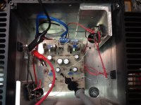
Here is an example test setup
I clamp them to a chunk of metal. They don't drift much with temperature,
and it gives me the time to measure other things as well.
Since 19V is a common switching supply for laptops and is the same voltage
as the Vds in the amplifier, use that as the voltage and find the Vgs which
gives you 0.50 Amp current. It will generally be in the range of 6 to 11 volts.
Check out the diagram in the first quoted post. For this project, this is the simplest way to go. 🙂
Did someone post schematics for a VGS matching test jig?
Regards,
Dan 🙂
Yes
http://www.diyaudio.com/forums/pass-labs/276711-sony-vfet-amplifier-part-2-a-26.html#post4394173
Best regards
Can't quite recall if it was for MOSFETs or our beloved VFET. Did someone post schematics for a VGS matching test jig?
Regards,
Dan 🙂
You can check Post #214 by Papa.....
You must have 2 power supply and must turn on the
Vgs first before you power up the main rail.
Sorry for the delay in posting but here is results for JA vs KE parts
VDS=20V, VGS @ 0.5, 1 and 1.5A
KE33 (Acronman)
(1) 8.1, 7.06, 6
(2) 8.65, 7.75, 6.53
(3) 9.02, 7.93, 6.92
(4) 8.36, 7.3, 6.27
(5) 8.41, 7.4, 6.42
(6) 8.8, 7.82, 6.9
JA33 (EternalHong)
(1) 11.76, 9.98, 8.3
(2) 10.27, 8.34, 6.47
(3) 10.61, 8.46, 6.36
(4) 10.55, 8.59, 6.65
VDS=20V, VGS @ 0.5, 1 and 1.5A
KE33 (Acronman)
(1) 8.1, 7.06, 6
(2) 8.65, 7.75, 6.53
(3) 9.02, 7.93, 6.92
(4) 8.36, 7.3, 6.27
(5) 8.41, 7.4, 6.42
(6) 8.8, 7.82, 6.9
JA33 (EternalHong)
(1) 11.76, 9.98, 8.3
(2) 10.27, 8.34, 6.47
(3) 10.61, 8.46, 6.36
(4) 10.55, 8.59, 6.65
This evidence that the linearity of the KE is different to the JA. But also does mean that the value at 1.5 A are similar in both groups.
This findings could suggest that in the upper part of the curve they are more similar.
I formulate a question: In the way to look for the better coincidence in the more linear work. Could we rise the current of the devices when paralleled them?
This findings could suggest that in the upper part of the curve they are more similar.
I formulate a question: In the way to look for the better coincidence in the more linear work. Could we rise the current of the devices when paralleled them?
Sorry for the delay in posting but here is results for JA vs KE parts
VDS=20V, VGS @ 0.5, 1 and 1.5A
KE33 (Acronman)
(1) 8.1, 7.06, 6
(2) 8.65, 7.75, 6.53
(3) 9.02, 7.93, 6.92
(4) 8.36, 7.3, 6.27
(5) 8.41, 7.4, 6.42
(6) 8.8, 7.82, 6.9
JA33 (EternalHong)
(1) 11.76, 9.98, 8.3
(2) 10.27, 8.34, 6.47
(3) 10.61, 8.46, 6.36
(4) 10.55, 8.59, 6.65
Thanks for posting!
It's a pity, they differ that much from the Acronman VFETs. If I interpret right, they have halve the Yfs of the Acronmans.
KE33 need around 2 volts lower Vgs to change from 0.5 to 1.5 Ampere.
JA33 need around 4 volts lower Vgs to change from 0.5 to 1.5 Ampere.
Still not sure, they are the real deal.....
This evidence that the linearity of the KE is different to the JA.
The way I read it, the linearity is roughly the same. If you check the value between each set of three steps, they are roughly the same. Only the size of the steps differs between the two types, so that´s a gain difference, not a linearity difference.
Jan
Thanks for posting!
It's a pity, they differ that much from the Acronman VFETs. If I interpret right, they have halve the Yfs of the Acronmans.
KE33 need around 2 volts lower Vgs to change from 0.5 to 1.5 Ampere.
JA33 need around 4 volts lower Vgs to change from 0.5 to 1.5 Ampere.
Since they are used as followers and feedback is available, the differences will
come out less than you might think. Some second harmonic, which can be
nulled in a number of places, including the Cascode feedback.
The way I read it, the linearity is roughly the same. If you check the value between each set of three steps, they are roughly the same. Only the size of the steps differs between the two types, so that´s a gain difference, not a linearity difference.
Jan
Did you looked at only the part of 1,5A is the same but not the curves belonged to the 0.5A if you note, the transconductance is so different. What means? Freddy measured three points the lower current is more different. Other situation happen with high current but maybe the tendency of the trace is more similar with higher current and the better linearity could be then.
The other comments of Nelson became like fresh water, the cancellation of 2th in other different parts of the amp. The feedback net. This calm us.
- Home
- Amplifiers
- Pass Labs
- Sony vFET Amplifier Part 2