I like your power connector blocks.
Too many hard solder everything and then have problems fault finding
having to de solder everything.
Too many hard solder everything and then have problems fault finding
having to de solder everything.
Does anybody know why there are two 47.5K resistors parallel to C5 an C6?
Is it a bit DC coupled this way or do you call it capacitor coupled?
Is it a bit DC coupled this way or do you call it capacitor coupled?
It passes DC, although at a lower gain. The caps are there to hold the
DC bias value between the Gates of the outputs and the output of the
front end while maintaining a low impedance AC path between all points.
😎
DC bias value between the Gates of the outputs and the output of the
front end while maintaining a low impedance AC path between all points.
😎
Super nice.
😎
Thank you, Sir!
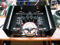
More progress and all good news. Did all the voltage checks and biased up the front end. No drama.
Couple clarifying questions:
- The 1.2V drop for R5/R6 is an intermediate value and the final target is 1.5V after leisurely warmup, correct?
- T18 (offset) was super duper twitchy and could vary ~500mV with some pressure on the trimpot or blowing on the devices. I could get it to ~60mV, but I don't have much confidence it'll stay there. Normal for this point?
- The 2nd draft 8/8/16 pdf refers to R6 (T9 and T10) voltage drop. This should be T8 and T9, correct?
Next I'll install the VFETS - wish me luck!
Below you can see my chassis arrangement and signs of life.
BK
Attachments
Thank you, Sir!
More progress and all good news. Did all the voltage checks and biased up the front end. No drama.
Couple clarifying questions:
- The 1.2V drop for R5/R6 is an intermediate value and the final target is 1.5V after leisurely warmup, correct?
#Correct, you want 1.5V
- T18 (offset) was super duper twitchy and could vary ~500mV with some pressure on the trimpot or blowing on the devices. I could get it to ~60mV, but I don't have much confidence it'll stay there. Normal for this point?
#Correct again. After you get to 1.5V you should be able with some playing with both pots to get it closer to Zero. The offset can jump around very quickly, a lot, with slight adjustments. Steady hand needed. 50mv is good though. You will have to adjust offset again with the V-fets.
- The 2nd draft 8/8/16 pdf refers to R6 (T9 and T10) voltage drop. This should be T8 and T9, correct?
#I found the instructions to be correct. R5 are test points T6 and T7 and R6 are T8 and T9.
Next I'll install the VFETS - wish me luck!
Below you can see my chassis arrangement and signs of life.
BK
See your quote above for what I found biasing mine.
You are very close. You will not be able to bias the V-fets to where they should be without 1.5V across R5 and R6. I almost forgot to mention, great looking build. Clean the pins of the V-fets to remove any grease before soldering. It is going to be hard fooling with grease not to get it on everything you touch. I used a q tip and alcohol and then soldered.
Last edited:
Next I'll install the VFETS - wish me luck!
Below you can see my chassis arrangement and signs of life.
BK
Beauty build & excellent wiring quality.
Any main power wire with bulb " tester" at hand for first start up ?
Congratulations and big magic smoke !


Beauty build & excellent wiring quality.
Any main power wire with bulb " tester" at hand for first start up ?
Congratulations and big magic smoke !
I do believe I see a variac in the picture.
You did the All Black "murdered" interior perfectly with those caps! I love it! Is that the 4U chassis?
I do believe I see a variac in the picture.
Just interested by your amp inside
now i see variac and Variac as well 😀
Have fun !
Greetings
Thanks, guys. Been monitoring for the last few hours and everything is rock solid, so I think all is well so far.
Yep, that's the 4U chassis + TeaBag 40mm PSU board and a 400VA SumR transformer wound extra beefy for Class A. I should have gone with black front panel to complete the murdered theme!
I use the variac with a low amp fuse and dial it up quickly to a position I've marked for my particular mains output. Bulb circuit for initial startup is probably a really good idea, but my impression is that following NP's instructions pretty well de-risks gotchas at this point.
BK
Nah, it actually has a lot of silver inside too, and I prefer a silver front panel!
Variac ll
Variac ll
Thanks, guys.
Yep, that's the 4U I should have gone with black front panel to complete the murdered theme!
BK
- The 2nd draft 8/8/16 pdf refers to R6 (T9 and T10) voltage drop. This should be T8 and T9, correct?
BK
After reading the instructions more carefully this morning I believe you are correct, typo. Later in the instructions Mr Pass definitely defines R6 test points as T8 and T9.
Should the input be shorted during front end or output biasing?
Could open inputs have contributed to my T18 sensitivity during front end biasing?
BK
Could open inputs have contributed to my T18 sensitivity during front end biasing?
BK
Should the input be shorted during front end or output biasing?
Could open inputs have contributed to my T18 sensitivity during front end biasing?
BK
I did not short mine. The offset is just very sensitive. A little movement moves the offset a lot. Mine would go from mv to many volts with just a little movement of the pots. Your observation is exactly what I found. Proceed.
I did not short mine. The offset is just very sensitive. A little movement moves the offset a lot. Mine would go from mv to many volts with just a little movement of the pots. Your observation is exactly what I found. Proceed.
Thanks wdecho. Question still remains - is it preferable here to short the input during the bias procedures? I want to think yes, but would be great to get the official word.
BK

- Home
- Amplifiers
- Pass Labs
- Sony vFET Amplifier Part 2