
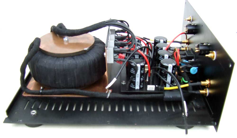
Here she is outside the case for better visibility and to answer your questions. There are 20 caps here in total.
Joe
tip : when using isolation tape - use cloth one (Tesa?)
it's nicer to eye , and will not slip/move later from heat , as plastic one
it's nicer to eye , and will not slip/move later from heat , as plastic one
Last edited:
dunno
some pooftah here is in recent years advocating their use , as main reservoir caps (when value is adequate for circuit) and as final bypass caps in rails ......
In PSU section do they work as a replacement of transformer snubbers (eliminate ringing).
Or they are for different role.
Should I choose the highest mf value I can fit to my chassis or is there a maximum mF value I should use?
Motor run is film cap, most you can fit or a good film cap would work. A motor run is suggested because of quality vs cost. Some build tube PS sections only using motor run caps, no electrolytics. Electrolytics are a lot of mf for small cost.
Last edited:
Motor run caps actually have pretty good performance. They also can be pretty compact for the non-electrolytic capacitance that they have.
Its common to see DIYers use them, especially in SET tube amplifiers. Since the SIT devices share a lot of characteristics with triodes it comes as no surprise that someone would think to also install such caps in the power supply to reduce sonic issues of the supply. There is a camp of thought that all power supplies are coupling capacitors. If you subscribe to that (I don't; our amps can run and actually sound pretty good with no filter caps in the output section at all) then the caps make a lot of sense. Even if you don't, the additional higher performance bypass essentially extends the bandwidth of the power supply much higher- it still makes sense.
Its common to see DIYers use them, especially in SET tube amplifiers. Since the SIT devices share a lot of characteristics with triodes it comes as no surprise that someone would think to also install such caps in the power supply to reduce sonic issues of the supply. There is a camp of thought that all power supplies are coupling capacitors. If you subscribe to that (I don't; our amps can run and actually sound pretty good with no filter caps in the output section at all) then the caps make a lot of sense. Even if you don't, the additional higher performance bypass essentially extends the bandwidth of the power supply much higher- it still makes sense.
Hi. After searching unsuccessfully, wish to ask...how much current flows through Q5 & Q6 ?, I would be using 2SK2013 & 2SJ313.
TIA.
TIA.
What for are the Run motor capacitors in this project?
More Snake oil inside?
One question to Uncle Ralph or Uncle Aleksandar:
In follower mode like this amplifier, Do have triode shape transference curve or are they transparent in the amplifier chain?
More Snake oil inside?
One question to Uncle Ralph or Uncle Aleksandar:
In follower mode like this amplifier, Do have triode shape transference curve or are they transparent in the amplifier chain?
Last edited:
Is that 4 x 12,000uf + 2 motor run caps per channel ?
Cantilope gave his blessing for me to answer for him. I am pretty sure he is using 60K uf per rail plus one 40uf MR. That's 4 15K uf per rail, 8 per channel. A serious PS.
That's quite a number of caps to fit into one box.
Thanks.
Sent from my HTC One E9PLUS dual sim using Tapatalk
Thanks.
Sent from my HTC One E9PLUS dual sim using Tapatalk
That's quite a number of caps to fit into one box.
Thanks.
Sent from my HTC One E9PLUS dual sim using Tapatalk
He is building dual power supplies. I built mine with one PS section but split the rails using 2 resistors and 2 extra caps along with MR caps per F6 BAF talk. A compromise but it should help. Page 15.
http://www.firstwatt.com/pdf/art_f6_baf.pdf
Mr Pass used 3 caps per rail making 4 rails. I used 4 caps instead of 3 and then installed a MR cap. This is commonly done on tube PS sections for better channel separation, splitting the last stage into two using a resistor to separate the channels some and another cap.
Last edited:
Hi. After searching unsuccessfully, wish to ask...how much current flows through Q5 & Q6 ?, I would be using 2SK2013 & 2SJ313.
about 1.5V across R5 and R6 at 47 ohms = about 30 mA
😎
Hi,
I thought someone might find this useful. Here is my Digikey BOM for the DIY kit.Digikey BOM
I started soldering the DIY PCBs. So far, I found that follwing parts were missing in the BOM:
2 Bourns Pots 5K
2 Bourns Pots 500R
2 Resistors 47.5 R
^^ Yup!
To the latter question, if the curves were of no importance, than this project would not have the interest it does. In cases like this you don't need to know anything technical to know the answer, which is the same answer as to why tubes and the LP are still around decades after being declared 'obsolete'.
The reason I am on this thread is due to the curves and characteristics presented. It seems someone created a semiconductor that actually solved the problems that tube people have been complaining about for decades. And then they went out of production; my guess is due to some very poor marketing.
They are not snake oil, although the audible effects will be subtle, like many things in high end audio.What for are the Run motor capacitors in this project?
More Snake oil inside?
One question to Uncle Ralph or Uncle Aleksandar:
In follower mode like this amplifier, Do have triode shape transference curve or are they transparent in the amplifier chain?
To the latter question, if the curves were of no importance, than this project would not have the interest it does. In cases like this you don't need to know anything technical to know the answer, which is the same answer as to why tubes and the LP are still around decades after being declared 'obsolete'.
The reason I am on this thread is due to the curves and characteristics presented. It seems someone created a semiconductor that actually solved the problems that tube people have been complaining about for decades. And then they went out of production; my guess is due to some very poor marketing.
I think the motor caps people generally use are Motor Start caps not Motor Run caps but people seem to use the terms interchangeably.
Sorry, but motor run caps are what you want. The motor start caps are inferior in quality and are not what you want to use.
^^ Yup!
They are not snake oil, although the audible effects will be subtle, like many things in high end audio.
To the latter question, if the curves were of no importance, than this project would not have the interest it does. In cases like this you don't need to know anything technical to know the answer, which is the same answer as to why tubes and the LP are still around decades after being declared 'obsolete'.
The reason I am on this thread is due to the curves and characteristics presented. It seems someone created a semiconductor that actually solved the problems that tube people have been complaining about for decades. And then they went out of production; my guess is due to some very poor marketing.
Sorry master, or Uncle Ralph, you misunderstanding my post, first of all, I am very interested in this project, actually I got two kits.
Second, When y said uncle I not referring to you unrespectfully , In this way we said Papa to NP, thus when I ask to you "uncle", I know you are a referent for Us and the audio world. I Building an MA60 since long time ago. But I could not finish yet.
Respect to the curves, I not explained the idea without much details, In the case of this project with SITs, you noted that they are in the output section and, they are no "anode" or "drain" follower, they are cathode or source followers like current amplifiers. Now the question, Can you tell if the "triode" trace curve is the same in cathode or source follower. I see that in your atmasphere amps the circlotron of your property is cathode follower, what happen if in the yours you connect the out between the anodes of the triodes?
In other aspects I firmly say if I believe that determinate component could be a snake oil, If I am wrong, I deserve at least the explanation of why him uses this component that not seems exist in the original project. 😎
Last edited:
No offense taken!!
The curve is the same in cathode or plate follower. We have built both configurations. Its easy to hear the linearity of the triodes over that of pentodes. I expect something similar from this SIT amplifier.
With regards to the motor run caps- they have measurably superior performance to electrolytics. FWIW, I don't mind electrolytics like many audiophiles do. I think they need to be treated and used correctly and they will perform just fine.
But I have heard and measured the improvement in performance offered by adding some bypass in non-electrolytic form. As I stated earlier, the power supply will have superior HF performance, and by that I mean it will have a lower impedance to a higher frequency. This can be important; if the power supply does not have wider bandwidth than the circuit to which it supplies power, IMD can result and IMD is very audible to the human ear.
Thanks a lot for your findings and your information.
Jama said the other day that the capacitance of the PS is in the audio chain.
But an to low percentage of capacitance, 80 to 60000µF is representative in this case?
Should I think in add this components in our next projects?
The best regards for you Uncle and the rest of the gentlemen.
Jama said the other day that the capacitance of the PS is in the audio chain.
But an to low percentage of capacitance, 80 to 60000µF is representative in this case?
Should I think in add this components in our next projects?
The best regards for you Uncle and the rest of the gentlemen.
- Home
- Amplifiers
- Pass Labs
- Sony vFET Amplifier Part 2