Hi all,
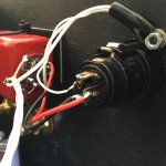
a Sony VFET with balanced inputs. The input transformer have a core in Super-Permalloy:
Audio Electronics - John Linsley Hood - Google Libri
Thanks Nelson for a great amp.
a Sony VFET with balanced inputs. The input transformer have a core in Super-Permalloy:
Audio Electronics - John Linsley Hood - Google Libri
Thanks Nelson for a great amp.
Attachments
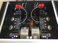
Congratulations on such a superb build! You choose a very clever layout for the dual mono build, keeping the right wires short, grounding everything correctly and tidily, even the XLR sockets!
I see that you've got two separate IEC input sockets, do you switch them individually too? Could we maybe see some more pics of your build?
I see that you've got two separate IEC input sockets, do you switch them individually too? Could we maybe see some more pics of your build?
Congratulations Claudio52 superb build.Hi all,
a Sony VFET with balanced inputs. The input transformer have a core in Super-Permalloy....
Could You please write more about input transformer , reference model characteristics etc. ?
What the balance signal trick ?
Thanks in advance 🙂
Attachments
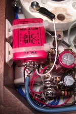
The transformer is shown in the picture. Euterpe Audio has long since stopped producing transformers. The primary and the secondary can be linked this Way:
Primary 1-4 ........... 1-4
Secondary 6-9 ........... 6-9
CC 2-3 7-8 ........... 2-3 6-7 8-9
Gain 1.5 ............ 0.8
Induct. pri. 400H ............ 400H
I have chosen the gain of 0.8. The impedence of the secondary that minimizes high frequency resonance is R2//12K. The impedence refereed to the primary is about 16K.
Tomorrow I will post picture of the amplifier inside.
Attachments
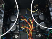
These are the pictures of the amplifier inside. I used the chassis of another project, an Aleph J. the amp had two 500VA transformers, two IEC input sockets, two switch and only balanced inputs. The Sony VFET has the same dual mono structure. The two transformers are 250VA. I hope the photos allow to understand the links.
Attachments
Would someone please refer me to the brand of temp control device (or the post mentioning such) that Nelson Pass recommended for use in maintaining heat sink temps during Vgs testing/matching of SITs?
He said it was about $50 or so.
I want to buy one.
PM me.
Thank you.
Msr. Mojo
He said it was about $50 or so.
I want to buy one.
PM me.
Thank you.
Msr. Mojo
Hi Nelson!,
What are they called?
I just looked at their website.
All I see are digital thermostats, but what is used to raise the temps of the heat sinks?
Is my memory fading, or didn't the unit you mentioned have everything needed to measure and control temps?
Accept my apologies if I misunderstood.
Thank you for your valuable time.
Respectively,
MM
amp stays on 3 sec. after switching off, ok?
other than my apleph, F5 and F6, the V-Fet stays on about 3 sec after switching off. The V-Fet has even less capacitance in the PSU than the others.
Is the amp so frugal to power consumtion or should i take it as a sign to recheck the bias?
tnx and best,
stefan
other than my apleph, F5 and F6, the V-Fet stays on about 3 sec after switching off. The V-Fet has even less capacitance in the PSU than the others.
Is the amp so frugal to power consumtion or should i take it as a sign to recheck the bias?
tnx and best,
stefan
if you set bias per prescribed , everything is ok
remember that amp is drawing less than other FW amps
remember that amp is drawing less than other FW amps
tnx : ), quite sure bias is set right, it´s just so unusual to my class A experience 🙂
best
st.
best
st.

SMPS for vfet amp
Power supply question:
Thinking of using a SMPS, like one of these, with an additional Schaffner FN 406-6-02 AC line filter. Two SMPS that I found:
Meanwell RSP-320-27 RSP-320-MEAN WELL USA Switching Power Supply
Connexelectronic SMPS300R 28V DC 300W Amazon.com: SMPS300R 28V DC 300W Switching mode power supply: Home Audio & Theater
Will I need TWO to get +/-27v for the VFET amp?
Is 300w enough power?
thank you!
Thinking of using a SMPS...!
Why would you want to do that? & besides, you need a positive-ground-negative rail, which these don't have unless you tie two together, which is an even worse idee. I would not go there.
The unregulated high capacitance PSU design of this amp is a big part of it's great sound signature.
Last edited:
I investigated using an SMPS for this amp. In many ways it is a good solution, see bwalso's 2nd Spring 2nd Spring -- another stab at the SE choke-fed Class A Power Amp The idea of switching the mains at 100KHz instead of 100Hz is very attractive in some ways. John Siau at Benchmark also uses an SMPS in his rather nice class AB amp.
However, after much investigation I will use a linear supply for this amp, because the SMPS supplies that I can find are not rated for the continuous current that this amp needs, and trying to get one even close is more expensive than a linear supply. The Meanwell medical SMPS series were the best I could find, you have to read the spec's very carefully for the SMPS's, they are not really designed for the sort of continuous load a class A amp imposes. If size or weight was more important to me, then I might choose otherwise. The linear supply is not bad, it's easy to implement and not too expensive.
However, after much investigation I will use a linear supply for this amp, because the SMPS supplies that I can find are not rated for the continuous current that this amp needs, and trying to get one even close is more expensive than a linear supply. The Meanwell medical SMPS series were the best I could find, you have to read the spec's very carefully for the SMPS's, they are not really designed for the sort of continuous load a class A amp imposes. If size or weight was more important to me, then I might choose otherwise. The linear supply is not bad, it's easy to implement and not too expensive.
Pass DIY Addict
Joined 2000
Paid Member
I think an SMPS is a very bad idea. First, you're violating the "simplicity" rule of this design by introducing a ton of things into the PSU that are not necessary. This has great potential to introduce lots of noise into your amp unless you already know that this is a quiet PSU.
Second, as pointed out above, you need a bi-polar power supply: -v, 0v, +v. The way to do this is to take two power supplies (with 0v and +v outputs) and connect the 0v from one supply to the +v of the other supply to form your "middle" 0v terminal. Depending on the internal configuration of the power supply, the 0v line is usually (though, perhaps not always) connected directly to ac ground on the primary side. Thus, you are creating a direct short circuit and are likely to have instant fireworks with two of these connected in the manner that is necessary for a bipolar power supply.
My advice would be to buy a toroid, a couple of rectifiers, and a pile of caps instead.
- Home
- Amplifiers
- Pass Labs
- Sony vFET Amplifier Part 2