I expect that many of you already know this..
I didn't, thanks for the tip.
I didn't, thanks for the tip.
I personally would not use contactspray on new blue Bourns cermet potentiometers.
Only for the old carbon Piher potentiometers i would consider to do that.
agree for contact spray
that's usually just last instance of cure , when pot is bad and you're going to replace it later
that's usually just last instance of cure , when pot is bad and you're going to replace it later
I personally would not use contactspray on new blue Bourns cermet potentiometers.
Only for the old carbon Piher potentiometers i would consider to do that.
Good point. I typically use a DROP of "dry" alcohol on ones that may have been on the shelf for a few years. It's quite possible for that alcohol to then draw water from the atmosphere, so, the circuit is left to idle and gently warm itself for a couple of hours. This dries out any alcohol.
There is every likelihood that this is overkill on new pots. However, "Overkill" is my middle name. My first name's "Excessive."
We discussed this a bit about halfway through the thread: http://www.diyaudio.com/forums/pass-labs/276711-sony-vfet-amplifier-part-2-a-36.html#post4811017
Your explanation is far more thorough though, Mescalero 🙂
Your explanation is far more thorough though, Mescalero 🙂
Thanks TEAM, mine arrived yesterday and it looks stunning [emoji1619][emoji1619]
Sent from my iPhone using Tapatalk
Sent from my iPhone using Tapatalk
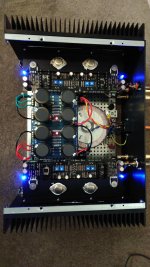
I have mine up and running. Thanks Nelson for your great design and generosity. Thanks also to everyone in the Diyaudio community that contributed to this great project!
It was a challenge to get the bias set accurately. One thing I ended up doing which I think helped a lot was to short T18 to ground then setup the output bias. This was done a once the FE was set for 1.5v drop as close as I could get it. Once the output was bias was accurately set I tweaked the T18 offset using P3 and P4 to get as close to 0v at the output as possible. This idea come from this post by Nelson :
http://www.diyaudio.com/forums/pass-labs/276711-sony-vfet-amplifier-part-2-a-178.html#post4811750
Attachments
Last edited:
I have mine up and running. Thanks Nelson for your great design and generosity. Thanks also to everyone in the Diyaudio community that contributed to this great project!
It was a challenge to get the bias set accurately. One thing I ended up doing which I think helped a lot was to short T18 to ground then setup the output bias. This was done a once the FE was set for 1.5v drop as close as I could get it. Once the output was bias was accurately set I tweaked the T18 offset using P3 and P4 to get as close to 0v at the output as possible. This idea come form this post by Nelson :
http://www.diyaudio.com/forums/pass-labs/276711-sony-vfet-amplifier-part-2-a-178.html#post4811750
And what about sound review?
@wdecho, only been listening today but its pretty awesome. Bass is very clean, midrange very authentic and terrific imaging. There is also details I am hearing on tracks I haven't head before.
You will cringe but I ended up using these terminals to make connections to the main boards :
http://au.element14.com/te-connecti...0000001472&searchView=table&iscrfnonsku=false
They are undersized for the holes but were very beneficial in terms of serviceability.
You will cringe but I ended up using these terminals to make connections to the main boards :
http://au.element14.com/te-connecti...0000001472&searchView=table&iscrfnonsku=false
They are undersized for the holes but were very beneficial in terms of serviceability.
@wdecho, only been listening today but its pretty awesome. Bass is very clean, midrange very authentic and terrific imaging. There is also details I am hearing on tracks I haven't head before.
You will cringe but I ended up using these terminals to make connections to the main boards :
http://au.element14.com/te-connecti...0000001472&searchView=table&iscrfnonsku=false
They are undersized for the holes but were very beneficial in terms of serviceability.
All that matters is it works without a problem. I found the V-fet to be extremely quick and dynamic.
DC offset problem
I've done the Part 1 and Part 2 tests and everything is fine up to there. With P3 and P4 fully counter clockwise I've got 0v across R5 and R6. At that point my DC offset is about 200mV. However as I increase the voltage across R5 and R6 the DC offset starts to rise alarmingly. Can anyone suggest what might be wrong?
I've done the Part 1 and Part 2 tests and everything is fine up to there. With P3 and P4 fully counter clockwise I've got 0v across R5 and R6. At that point my DC offset is about 200mV. However as I increase the voltage across R5 and R6 the DC offset starts to rise alarmingly. Can anyone suggest what might be wrong?
Those pots adjust both the current for the VAS and the DC offset.
Maybe you want to review the procedure for this adjustment.
Maybe you want to review the procedure for this adjustment.
Measuring at T6/7 and T8/9, I went about 100mv at a time, back and forth, to keep a near-balanced condition at all times.
Last edited:
Well I successfully got the voltages across R5 and 6 up to 1.5v with the DC offset at about 200mV. I suppose I was surprised at just how sensitive it is - the slightest movement of P3 or P4 is enough to send the DC offset up to 5 or 10 volts. Is that to be expected ?
I have similar experiences.
Especially, when I used fake 2SK170/2SJ74s.
Actually, in this case, it was impossible to set it correctly.
Now I have DC offset under 5mV.
Especially, when I used fake 2SK170/2SJ74s.
Actually, in this case, it was impossible to set it correctly.
Now I have DC offset under 5mV.
I have similar experiences.
Especially, when I used fake 2SK170/2SJ74s.
Actually, in this case, it was impossible to set it correctly.
Now I have DC offset under 5mV.
I'm using the DIYA kit of parts, not ones I've sourced myself.
I glued together them by their plain side.
Then mounted them under component side.
I was planning to use some silver-bearing epoxy to glue the 2SK170 & 2SJ74 together, touching. I also thought about a small copper strip going from top-to-top. Tektronix once used little machined gizmos to hold two cases face-to-face.
I'm about to begin building this.
Currently I'm using an Aleph J with DCB1 into Frugal Horns.
I'm anticipating that this may not have quite enough juice for the FH3s and I may need to add some gain via a preamp, any recommendations here, DIY or otherwise?
Jim
Currently I'm using an Aleph J with DCB1 into Frugal Horns.
I'm anticipating that this may not have quite enough juice for the FH3s and I may need to add some gain via a preamp, any recommendations here, DIY or otherwise?
Jim
- Home
- Amplifiers
- Pass Labs
- Sony vFET Amplifier Part 2