Bernhard, sorry for the long wait. A nice girl on the phone 😱
Yes, I think you got your reasoning right. Can you replace Q131, for instance with a BD139, temporary just to try the quiescent no-signal conditions?
Jan Didden
Yes, I think you got your reasoning right. Can you replace Q131, for instance with a BD139, temporary just to try the quiescent no-signal conditions?
Jan Didden
Ok,... or better: Not ok...
After putting a BD244C in place of the 2Sa835 it is still the same.
Just ordered 2 2SA835 for 8 EUR today 😀
Now I adjusted the offset pot, this works, and makes those 0,7V on both emitters disappear just a few mV left.
And sound is always distorted.
Maybe the NPN is dead ???
There is for sure no current flowing in the driver stage but why does offset adjustment work ?
Edit:
Now I measured C142 both sides voltage to ground, the good channel gives +1,2V and -1,2V and the bad channel +0,6V and 0V.
So is it wrong before the driving stage ?
Edit:
So the NPN is not dead and conducts, and the PNP is also not dead but does not conduct. (?)
Good news 
The signal on C142 both sides looks like a square on the bad channel and is a sine on the good.
The signal on C142 both sides looks like a square on the bad channel and is a sine on the good.
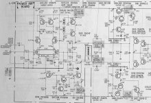
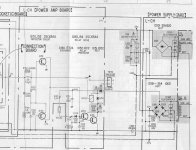
Jan,
do you have the schematic of the input section too ?


The test points in the output stage that shall have +/- 15-20V have healthy +/-18
do you have the schematic of the input section too ?
The test points in the output stage that shall have +/- 15-20V have healthy +/-18
The signal swing on both ends of R123 is much too big, as if there was no feedback...
Some part of the amp goes into clipping even on lowest volume
Some part of the amp goes into clipping even on lowest volume
Jan, thanks for the schematic.
Bernhard, if I may…
Usually, when I repair amps like that, I start measuring the safety resistors.
Lots of them here so make sure you discharge the supply caps before measuring as the remains of voltage have great influence on ohmic measurements.
I possible even disconnect the caps.
Somewhere you said R136 was 250 ohm or so. Could be leftover voltages. Or it could be broken.
Then I check all diodes. Mostly fairly simple with a diode meter. When in doubt I take them out or check the schematic for a low resistance parallel.
Then I check the transistors for shorts. All of them. Again when in doubt I unsolder them. Sometimes it’s a time consuming job but in many cases the only way.
Looks like a fairly nice amp BTW. 😉
/Hugo
I suggest you check that current source around Q111. I had a Technics amp with a similar problem (but without the oscillation). The amplitudes in the bad channel were much higher and the problem was a bad connection in the current source for the VAS.
Hugo,
very good idea...
R121 was very dead.
12k instead of 220.
Replaced it and bias is ok, distortion gone.
There are some other resistors already weak, as the mentioned 100ohm that measures 250...
So the other channel with weak bias will have a similar problem.
When I repaired amps it always was output transistors, first time I see this...
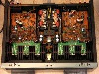
This amp is stuffed, no empty space...
This is the amp, but mine is in nice cosmetic condition 🙄
http://cgi.ebay.com/ws/eBayISAPI.dll?ViewItem&category=39783&item=5751475478&rd=1&ssPageName=WDVW
very good idea...
R121 was very dead.
12k instead of 220.
Replaced it and bias is ok, distortion gone.
There are some other resistors already weak, as the mentioned 100ohm that measures 250...
So the other channel with weak bias will have a similar problem.
When I repaired amps it always was output transistors, first time I see this...
This amp is stuffed, no empty space...
This is the amp, but mine is in nice cosmetic condition 🙄
http://cgi.ebay.com/ws/eBayISAPI.dll?ViewItem&category=39783&item=5751475478&rd=1&ssPageName=WDVW
megajocke said:I suggest you check that current source around Q111. I had a Technics amp with a similar problem (but without the oscillation). The amplitudes in the bad channel were much higher and the problem was a bad connection in the current source for the VAS.
How true...
Hope the low bias in the other channel is also dead resistor.
But already sounds nice.
So megajocke was correct about that CS.
The approach I take is a very practical one because I used to work with a friend who could look for hours at schematics before digging into the amp or whatever was broken. In these days I couldn't even read a schematic and I started measuring parts.
Together we repaired a lot of gear. He was the theoretical guy, I the practical one.
That friend died a few years ago so I was left on my own to read schematics. Little by little I understand parts of them now but the main action is always measuring.
So, this thread is a perfect example how to combine both approaches.
Nice amp, keep us posted.
/Hugo 🙂
Bernhard,
do yourself and that beauty a favor and check the solderings on the driver boards. Sony is well know for invisible bad solderings.
Also, tighten the screws of the output transistors to make sure the collectors make good contact.
/Hugo
do yourself and that beauty a favor and check the solderings on the driver boards. Sony is well know for invisible bad solderings.
Also, tighten the screws of the output transistors to make sure the collectors make good contact.
/Hugo
Must the safety resistors be replaced by safety resistors ?
Or can I just replace with carbon and same watt ?
If those resistors fail without reason...
I plan to replace all safety resistors and all lytic caps on the driver board.
Or can I just replace with carbon and same watt ?
If those resistors fail without reason...
I plan to replace all safety resistors and all lytic caps on the driver board.
Yes, for obvious reasons. A resistor is cheaper than a transistor. 😉Bernhard said:Must the safety resistors be replaced by safety resistors ?
/Hugo
Netlist said:
Yes, for obvious reasons. A resistor is cheaper than a transistor. 😉
/Hugo
Hope I can get them...
http://de.farnell.com/jsp/endecaSearch/partDetail.jsp?SKU=341551&N=401
Click on Kataloginformationen.
Don't know if 0.33W is powerful enough though.
/Hugo 🙂
Click on Kataloginformationen.
Don't know if 0.33W is powerful enough though.
/Hugo 🙂
- Status
- Not open for further replies.
- Home
- Amplifiers
- Solid State
- Sony V-Fet Amp TA-N7B problem