Going to replace all the caps in the PSU board now - amazing how caps have decreased in size over 30 years. The new 1000uF 200V caps are a third of the height of the hulking big Nichicon originals!
This was my solution;
Build an adaptor board
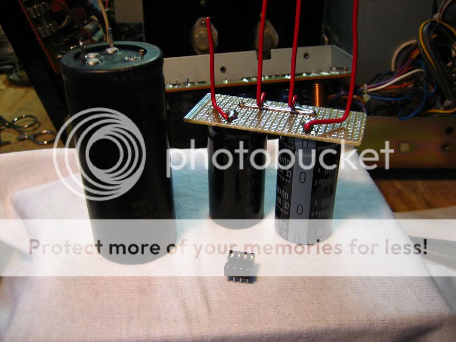
line up the wires to the original solder points

Solder 'em in!
That's a neat solution - tidy work! I'm taking the lazy way out however and am just going to extend the legs on the capacitors slightly. The 2200uF Panny FCs (same as you used I think!) are fine, but the 1000uFs need the extensions.
Unfortunately mine's requiring a lot more work to get up and running than yours alas - still it's been fun and I'm learning a lot! 😀
P.S. A tip which you might want to try out on yours, and which I intend to do on mine if I do get it working, is to replace all instances of the back-to-back (non-polar) caps in the signal path with same value (and a single unit in place of each pair of electros**) film caps (probably Wima MKS or MKP). Just about any film cap sounds better than an electrolytic, even back-to-back ones, so I think this will eek out an even better sound from the Sony. A simple non-destructive tweak. Shouldn't cost much either. Worth a try! The caps are:
C111/112/161/162
C201/214/251/264
C206/216/256/266
- John
** i.e. a pair of 4.7uf electros back-to-back can be replaced with a single 4.7uF film cap, obviously leaving out the two middle pads where the legs were originally joined for the electrolytic pair.
Last edited:
🙂
What do mean "null" lol ? Do you mean low as in below 0.50 ish on the meter when on a low ohms range ? which would be below 0.5 ohms.
25 volts for the tranny is fine to test... really 🙂 That gives -/+35 volts DC.
What do mean "null" lol ? Do you mean low as in below 0.50 ish on the meter when on a low ohms range ? which would be below 0.5 ohms.
25 volts for the tranny is fine to test... really 🙂 That gives -/+35 volts DC.
Null - I thought that was the proper word hahaha! Trying to be all fancy see 😉
Null as in absolute zero reading 🙂
Null as in absolute zero reading 🙂
As in 0.00 you mean. That's short.
If so we need to do careful checks to find exactly where and what.
Is that what you mean "short" ?
If so we need to do careful checks to find exactly where and what.
Is that what you mean "short" ?
What does your meter show John when you connect between the case of the transistors and each rail ?
Ah made a mistake Mooly - on the 200-ohm setting all read 0.00.
However on the 20K setting each output transistor reads approx. 3.0 from transistor case to either G or B+, with B- measuring slightly higher each time (i.e 3.5).
Is that good?
- John
EDIT: B- seems to rise to about 4.0
However on the 20K setting each output transistor reads approx. 3.0 from transistor case to either G or B+, with B- measuring slightly higher each time (i.e 3.5).
Is that good?
- John
EDIT: B- seems to rise to about 4.0
Last edited:
Not good... if they read 0.00 on the 200 ohms range. tbh they should read the same on the higher range as a short is a short. Does your meter read 0.00 if you short the leads together on all the ohms ranges
What meter is it ?
Does it read the same 0.00 if you do the same test using the diode range ?
How easy are they to get at ?
How easy to unsolder the 2 leads from base of each transistor in both channels to isolate them ?
If they are short then it's still an easy repair hopefully...
What meter is it ?
Does it read the same 0.00 if you do the same test using the diode range ?
How easy are they to get at ?
How easy to unsolder the 2 leads from base of each transistor in both channels to isolate them ?
If they are short then it's still an easy repair hopefully...
I may have to try that polar to non-polar replacement--I know that another TA-F6B owner had his amp restored at a shop, where they then tested it and it put out 176W/channel at rated distortion (100w/chan. advertised I believe).
Yea, yours it taking a lot more work to get back into service, but it will be worth it! One thing I want to do is go back in there and swap out some resistors just as a precautionary measure near the power transistors. They were looking a little... toasty... from what I can remember.
Yea, yours it taking a lot more work to get back into service, but it will be worth it! One thing I want to do is go back in there and swap out some resistors just as a precautionary measure near the power transistors. They were looking a little... toasty... from what I can remember.
OK just tried again (it should be noted that caps have been removed from the PSU PCB board as I thought they might be affecting readings, and they need replacing anyway - C802/803/801/805).
On the 200-ohm (lowest setting) I get nothing - not even a 0.00. Just a .0L
Same on the 2K setting.
On the 20K setting I get the readings mentioned in post 167.
If I switch to the diode setting, I get:
.655 - B+
1.435 - B-
.802 - G
The meter is a Academy Precision Gold PG017.
Fortunately the output transistors are not soldered in but use a tight socket system. Should be fairly easy to get them out (he says!).
- John
I may have to try that polar to non-polar replacement--I know that another TA-F6B owner had his amp restored at a shop, where they then tested it and it put out 176W/channel at rated distortion (100w/chan. advertised I believe).
Yea, yours it taking a lot more work to get back into service, but it will be worth it! One thing I want to do is go back in there and swap out some resistors just as a precautionary measure near the power transistors. They were looking a little... toasty... from what I can remember.
Wow 176W! - I guess that's the culmative effect of all-new and better technology capacitors, and perhaps they replaced the output transistors too.
Yes I am really looking forward to hearing her in action - let me know if you replace those caps and what you're findings are.
OK... lets be sure.
1. Meter on diode range. If you short your leads together on the diode range what does the meter show ?
2. Still on diode range connect either lead to the case of one of the output transistors in one channel. Connect the other lead to the positive supply.
Whats the reading ?
3. Now move that lead to the negative rail.
Whats the reading ?
4. Repeat for the other channel moving the lead connected in step 2 above to the case of either transistor in the channel. (The collectors are joined so it doesn't matter which one of the pair you pick)
What are the two readings for this channel ?
I'll look in again in a little while.
Righto.
1) Diode range shorted together .000
2) .656 (+)
3) 1.312 (-)
2b) .650 (+)
3b) 1.308 (-)
- J
P.S. Daft question: Mooly these readings are without the 'Naim donar' PSU connected, a powerless amp - that correct?
1) Diode range shorted together .000
2) .656 (+)
3) 1.312 (-)
2b) .650 (+)
3b) 1.308 (-)
- J
P.S. Daft question: Mooly these readings are without the 'Naim donar' PSU connected, a powerless amp - that correct?
It wouldn't make any difference if the Naim were connected or not.
Those readings look OK... so I think the next step has to be to conect the Naim PSU and see what happens. Use a bulb as described and have nothing else connected to the Sony, no speakers etc.
Those readings look OK... so I think the next step has to be to conect the Naim PSU and see what happens. Use a bulb as described and have nothing else connected to the Sony, no speakers etc.
Whew well that's good to know 🙂
So is the Naim PSU test just to see if anything goes 'pop' when power is applied, or will I need to take some measurements?
Unfortunately I've used up my energy for the day - on a good day can manage an hour or two of DIY work before the 'brain fog' sets in and I just have to go lie down.
Looking forward to another chapter tomorrow - thanks for all the help today folks, and Mooly I reckon I owe you a beer or 4!!!
- John
Lol, nothing should go pop hopefully.
We take some basic measurements, maybe even getting as far as listening to it 🙂
One step at a time though... something like this,
1. Connect up the Naim PSU (making 100% sure polarity is correct)
2. Depending on the outcome of the next step determines where we go from here.
3. Switch on... observe... the bulb should maybe glow dimly. If it's bright switch off and we look for a fault.
4. If it's dim it's looking good 🙂
All sounds good Mooly - look forward to that little episode tomorrow 🙂
See you tomorrow folks!
- John
See you tomorrow folks!
- John
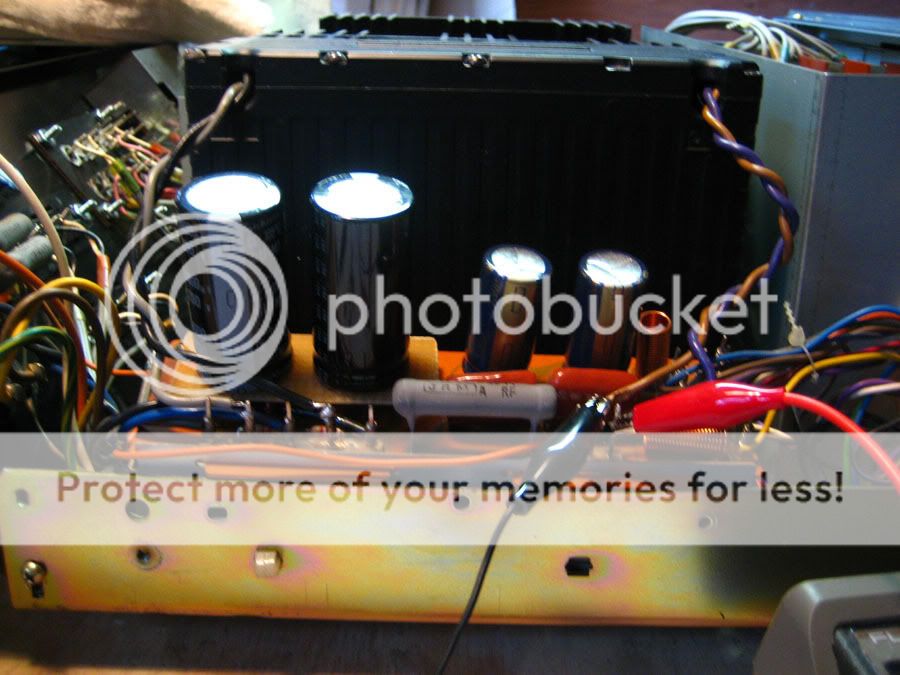
Afternoon!!!
Right I think I have this all set up correctly:
1) Fuse taken out of the 'PSU donar amp' and replaced by a 100W bulb across the terminals.
2) G / B+ / B- connections on Sonys PSU board connected respectively to 0V / Vout+ / Vout on the donars PSU.
3) Anything you can see that I've missed, or switch on time?
Frankenamp!
An externally hosted image should be here but it was not working when we last tested it.
- Home
- Amplifiers
- Solid State
- Sony TA-F6B PSU repair