Also i should mention i think to the best of my knowledge the pre amp is working fine, connecting headphones yields clean undistorted sound, all tone controls work, no pops or crackles.
Your problem is oscillation, so it's not going to be diagnosed with only a multimeter. There can be several reasons for this, aged semis (replacement may require adjustment of values of compensating capacitors), problematic wiring or contacts (power and signal ground couple through the ground in the wiring loom to prevent ground loops, there is no connection on the power amp PCB, which also means there will be problems if the amp is powered up without the input connector to the PCB plugged in), or even oscillation in the line amp portion.
Besides that, there are several versions of the board with various component values and some components fitted on some, not on others. See if you can find the Japan version to get a clue. In your case, the bias has FAR too much adjustment range. Bias voltage on the gates of the VFETs must NEVER fall below that of the sources, in fact should not come closer than around 8V with respest to source (main power) voltage. Eg, if main power is say 44V, bias voltage should go from 80-something (almost equal to the bias supply) to not less than about 56V. There are resistors which set the range together with the pot value. These of course are unloaded values (no VFETs, hence no bias current). IMPORTANT!!!! HIGHEST bias voltage number = lowest bias current. Lowest bias voltage number = highest bias current. Also there is a cap in parallel with the bias generating resistors in the early versions of this amp. In the later ones it is removed, which I have found sometimes leads to oscillation when the semis are aged. The old version had an electrolytic fitted, I usually put a small 0.47u foil cap (WIMA).
Is it wise to add this on to a TA-4650 as well or only if you have an issue? And was this listed on the schematics for both amps or just the 5650?
Athanasios
Last edited:
My meter can read close to 20Mhz is it possible to find oscillation this way? After i read this i went and put the test probes of my meter in the speaker output terminals and i get no reading but as soon as i short the inputs i get 87khz on the left and 90.3khz on the right channel.
That maybe the oscillation ilimzn is talking about?
I wonder if you find the same frequencies when you measure the bias or on the Gates and source?
Athanasios
I wonder if you find the same frequencies when you measure the bias or on the Gates and source?
Athanasios
I get the same frequencies on source and drain but nothing on the gate. Source to gate gets 104.8khz and varies with the trimmer. Without being able to see the waveform on a scope though i have to no idea what it is or if its also got other frequencies underneath it.
Right, Did you try adding that deleted cap ilimzn mentioned that I asked about then re measure?
nashou
nashou
I haven't yet tried the cap as i don't have any 0.47uf film caps on hand and i haven't had a look at the schematic yet to work out where they need to go. That said if it fixed the problem i'd view it as a band aid solution because if the amp used to work without it something has obviously gone out of spec so i'd like to find it and replace it first to ensure continued reliability of the amplifier. Then once i have done that if ilimzn recommends adding the capacitor to make the unit more reliable i will do so. My end goal is to make this thing as reliable as i can.
I agree.
Finding issues that arise that were not there before that show up after some
upgrades is a pain the **** !!!
When you got the amp everything was fine or were some known issues?
Nashou
Finding issues that arise that were not there before that show up after some
upgrades is a pain the **** !!!
When you got the amp everything was fine or were some known issues?
Nashou
I bought this amplifier from a yard sale with its matching tuner and manuals for $10 aud, it was in unknown working condition. I later met the owner who told me it had been in their shed playing radio a few months earlier. When i got it, it powered up and on a quick test played sound out both speakers although the bias was a mess jumping all other the place. I removed the vfets and one tested slightly faulty, one meter said it was ok, the other said it wasn't. I found burned resistors all over the amplifier board, some had been replaced on the channel with the dead v-fet, all capacitors on this channel has the plastic on them shrinking. It was at that point i test and found the voltage issue, after that i proceeded to recap the whole unit, replace anything burnt, update resistor values etc to the sony service bulletin, implement the voltage doubler mod, the double diodes on the amplifier board and a ton more. Its fixed up a lot of things but the s-g issue still remains. I suspect that if the v-fets where installed the extra load on the circuit might sort things out because it was working in this state before i gave it a overhaul but due to their rarity i cant play like that or it could cost me.
Last edited:
I see, have you looked at any of the small transistors at all?
Also maybe go over all the solder joints for each transistor and diode etc. maybe a
cold solder joint etc if you already haven't.
At least it will keep you busy while someone with more experience on these helps . 😉
I should see which way the trimers need to be turned on my 4650 to get max voltage at the S to G . But now that I think of it I have only been testing this with the Jumpers out as recommended by echowars at AK. I asked why I should do this and he said " just incase the preamp section doesnt mess any of the readings up" ? Hmm ........
I've re soldered probably 80% of the connections on the amplifier board just to be sure, i haven't test all of the transistors but i have checked all of the 2sa705's, 2sa835's and 2sc1663's on both channels and they were all ok. I will test the rest its just a matter of doing it as its tedious work. I also have the sony st-4950 tuner to work on which i am doing at them moment, it works fine so its a matter of cleaning, a recap and i'm also converting the backlights to led so I've got to build a basic rectifier circuit and work out how to mount the leds for that as well. With the original trimmers installed anti clockwise got the highest voltage and clockwise got the lowest.
I think I just replied to your thread over on AK, but just in case... I had same symptoms.
Read here and proceed with extreme caution at your own (or your VFET's) risk.
Read here and proceed with extreme caution at your own (or your VFET's) risk.
@nashou66 It is coming close to completion, although i am still having issues with the voltages and some further test revealed more voltages are wrong. I did the voltage mod and the cleared up the imbalanced voltages caused by the power supply drifting to one side and it also appeared to initially fix the S-G issue. However its still not right, with the pre and amp inputs separated everything appears ok, as soon i connect the amp and pre or short the amplifier inputs the polarity of s-g reverses and the voltage goes down, at the same time the voltage of the positive and negative bias supply is affected. I have been working with Joshvi trying to track down the issue and he is a massive help. Heres a few photos that show whats going on and how i implemented the voltage doubler mod on the TA-5650. I plan to do a post showing the restoration of both the TA-5650 and the sony st-4950 tuner that came with it once and if i get the amplifier up and running. I've been following your thread over at ak, all the best with your 4650, looks like you're having a little more luck then me at this point.
Sd6
An externally hosted image should be here but it was not working when we last tested it.post image
An externally hosted image should be here but it was not working when we last tested it.image hosting 20mb
An externally hosted image should be here but it was not working when we last tested it.gifs upload
An externally hosted image should be here but it was not working when we last tested it.image upload no limit
I've replied to the thread over at ak but i will also post a copy here just so members here don't miss out,
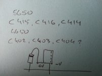
Sorry i haven't posted any updates the last few days, every chance I've had to look at the amp keeps getting taken away. I'll grab those measurements for you tomorrow Smufer and see if i get AC, i do recall testing at some point and i think i did but cant recall what voltage. I too have considered doing exactly what you did and installing the v-fets. The reason i thought this is the amplifier did play for the very brief moment i tried it before i touched it, the bias was a mess but it did work. Once i pulled the v-fets i found one seems semi faulty, potentially still working but damaged and the voltages to be all weird? On one meter it would read open circuit as it should, on the next meter i'd get 0.99v and then 0.55v reversed, its to late at night to remember what pins that was on. After the reccap and double diodes on the amplifier board along with replacing everything else i hoped it would fix the issue but it didn't. First i'm going to try replacing all the small value capacitors film and ceramic, i have had troubles in other amplifiers before that had me tearing my hair out only to find a small value cap that would appear fine then do funny things under certain conditions. Next it has been suggested to me to add a small value cap to the place on the board near the bias adjusters, there is the screen printing for it labeled c306 and c356, they are not mentioned in the service manual, . Apparently earlier versions of the amplifier had this capacitor and ilizm who suggested it had found that some of the newer models that had oscillation problems were solved by adding it back to the circuit. What i do know is i defiantly don't want to blow anymore v-fets, i was extremely lucky that Joshvi happened to have a used one of the rank i needed and was willing to part with it, it would be a nightmare trying to replace all 8 of them!
Sorry i haven't posted any updates the last few days, every chance I've had to look at the amp keeps getting taken away. I'll grab those measurements for you tomorrow Smufer and see if i get AC, i do recall testing at some point and i think i did but cant recall what voltage. I too have considered doing exactly what you did and installing the v-fets. The reason i thought this is the amplifier did play for the very brief moment i tried it before i touched it, the bias was a mess but it did work. Once i pulled the v-fets i found one seems semi faulty, potentially still working but damaged and the voltages to be all weird? On one meter it would read open circuit as it should, on the next meter i'd get 0.99v and then 0.55v reversed, its to late at night to remember what pins that was on. After the reccap and double diodes on the amplifier board along with replacing everything else i hoped it would fix the issue but it didn't. First i'm going to try replacing all the small value capacitors film and ceramic, i have had troubles in other amplifiers before that had me tearing my hair out only to find a small value cap that would appear fine then do funny things under certain conditions. Next it has been suggested to me to add a small value cap to the place on the board near the bias adjusters, there is the screen printing for it labeled c306 and c356, they are not mentioned in the service manual, . Apparently earlier versions of the amplifier had this capacitor and ilizm who suggested it had found that some of the newer models that had oscillation problems were solved by adding it back to the circuit. What i do know is i defiantly don't want to blow anymore v-fets, i was extremely lucky that Joshvi happened to have a used one of the rank i needed and was willing to part with it, it would be a nightmare trying to replace all 8 of them!
hi guys can you help out with my sony ta 5650 it not regulating the voltage I am getting 62v dc at both the 20vdc and 100vdc at the power supply voltage board, the voltages coming from the rectifier board are correct i.e. 46 volts and -46v dc also I am getting 33 volts on the test point where it say it should be 3.9 v ac for the light bulb. To be on the safe side none of the other board like the tone/eq boards, the power board or the output are connected to the powersupply board, your help will be appreciated, thanks!
hi guys can you help out with my sony ta 5650 it not regulating the voltage I am getting 62v dc at both the 20vdc and 100vdc at the power supply voltage board, the voltages coming from the rectifier board are correct i.e. 46 volts and -46v dc also I am getting 33 volts on the test point where it say it should be 3.9 v ac for the light bulb. To be on the safe side none of the other board like the tone/eq boards, the power board or the output are connected to the powersupply board, your help will be appreciated, thanks!
I hope I'm on time.
No expert but first take off the vFETs until you are 100% sure that everything' s OK.
Study the schematics and PS board from the manual available and then check all the resistors, caps and transistors (specially Q401 to 403) for obvious damage. If you are unable to find the fault(s), check again the voltages from every point possible of the PS board and draw a map of tensions to ground...that way we may be able to find the culprit(s). Most possible a couple of transistors/resistors combination.
Good luck.
M.
Last edited:
- Status
- Not open for further replies.
- Home
- Amplifiers
- Solid State
- Sony TA-5650 voltage doubler mod?