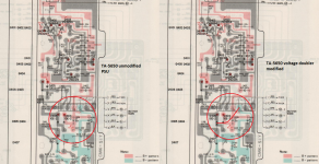
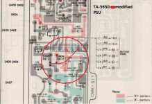
In the process of restoring a TA-5650, I've read about unsymmetrical loads causing the power supply to fall on its face in the ta-4650 and apparently the 5650 has the same design flaw. I have yet to fully finish mine and test this to see if its an issue on mine but i figure i should do the mod as a preventative anyway as i want this unit to be as reliable as possible. I can find info on the mod for the 4650 but not the 5650. I've created a modified version of the schematic to show where i think the extra diode needs to go.
Attachments
This will unbalance the + - 82V rails and upset the drivers. The reason they fail is the two pump capacitors go high ESR. No other reason.
If your 'mod' was a Sony 'mod', I would have picked it up in the training sessions.
If your 'mod' was a Sony 'mod', I would have picked it up in the training sessions.
Thanks for response, glad i seeked more information, i didn't create this mod it was one that has been discussed a lot in other forums. Quote from another forum regarding a 4650, the diode mod apparently was designed to rectify this, there was some mention of the same thing in the 5650 but no one went into more detail. If all it is though is the pump capacitors the whole unit has been recapped so that will no longer be an issue for me anyway.
"Hello,
I started restoration of a SONY TA-4650 V-FET amplifier.
However I have one Problem with the power supply which I can not get solved:
The +/- 75 Volt changes slowly to +83V/ -67 Volt.
I changed capacitors, all double-diodes, supply diodes, load resistors on the +/-75Volt rail. I also changed BIAS-transistors, making sure that their current and Hfe in upper and lower half is as close as possible. After transtir changer to better matching ones the 'drift' is much much slower, but it is still there.
The charge-pump (voltage doubler) which creates the +/-75Volts keeps shifting voltage to one side, slowly.
I am currently having no VFETs in the amp - to be on safe side.
I also created the SONY TA-4650 supply in a SPICE simulation, with the same result. The voltage doubler shifts voltage to one side, if the supply is not exactly ( milliamp accuracy) loaded identically on both sides !
I think the voltage drop, after some time could lead to a too low Vgs and therefore rise of bias and potentially death of depletion mode VFETs."
This will unbalance the + - 82V rails and upset the drivers. The reason they fail is the two pump capacitors go high ESR. No other reason.
If your 'mod' was a Sony 'mod', I would have picked it up in the training sessions.
Good on you for the quickshot answer, quick keyboard but not do much thought out, so now go and do some thinking on what happens to the charge pump capacitors once an output stage fails (for which there are plenty other resons), and HOW they go high ESR. How many of these amps have you re-built and how many had the series RC filter resistors burned, and why?
Thanks for response, glad i seeked more information, i didn't create this mod it was one that has been discussed a lot in other forums. Quote from another forum regarding a 4650, the diode mod apparently was designed to rectify this, there was some mention of the same thing in the 5650 but no one went into more detail. If all it is though is the pump capacitors the whole unit has been recapped so that will no longer be an issue for me anyway.
"The +/- 75 Volt changes slowly to +83V/ -67 Volt."
You will still have this problem because without the VFETs fitted the driver stage has to source current to the output, including the ripple compensation networks and feedback. Without the diode mod the whole driver voltage generator is essentially floating between the main power supply rails so very little current imbalance will upset the driver rail balance. When the VFETs are fitted, only a very small fraction of this remains as most is sourced by the VFETs from the main power rails, but a small imbalance still remains.
The real problems here is that if anything overloads the bias supply, it collapses (also reverse polarizing some caps in the charge pump) and this is shared amongst the channels. Even hard clipping can do this and in fact a failure on one channel may easily result in the other failing too. Diodes from +44 to +85 and -85 to -44V should also be fitted to secure the best performance of the charge pump.
@ilimzn after reading post by both you and Joshvi i regard both of you as knowing a lot about these amps. Would it be possible for you post a modified version of the schematic to show where you recommend extra diode placement?. I'm mostly self taught with electronics and we are starting to go a little past what i know here and a vfet amplifier is not something I'd like to trust my own knowledge 100% on.
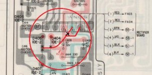
A very tired me after work didn't even notice i connected thst to -v, thanks for correcting it! anymore mods thats should be added to psu to make it more stable or is this about it?
The mod with two diodes is also a good idea.But the juntion of the diodes has to go to ground not -V !
Mona
Yes ,the junction goes to ground not -V
Awesome, i shall implement the mod soon then hopefully i can get this thing up and running once the vfet i need arrives. I've also got to work out whats going on with the source to gate voltages without the vfets installed. When tested with the bias set to max they would only reach around 5v. I haven't gone any further into testing yet, that was just a brief test after i finished recapping etc.
sd6, how is the restoration on this going? Did the diode mod work? Also what about the S to G voltage issue ? Resolved yet?
I'm about to add the V-fet's to my restored TA 4650 soon. I have a thread over at AudioKarma
Athanasios
I'm about to add the V-fet's to my restored TA 4650 soon. I have a thread over at AudioKarma
Athanasios
@nashou66 It is coming close to completion, although i am still having issues with the voltages and some further test revealed more voltages are wrong. I did the voltage mod and the cleared up the imbalanced voltages caused by the power supply drifting to one side and it also appeared to initially fix the S-G issue. However its still not right, with the pre and amp inputs separated everything appears ok, as soon i connect the amp and pre or short the amplifier inputs the polarity of s-g reverses and the voltage goes down, at the same time the voltage of the positive and negative bias supply is affected. I have been working with Joshvi trying to track down the issue and he is a massive help. Heres a few photos that show whats going on and how i implemented the voltage doubler mod on the TA-5650. I plan to do a post showing the restoration of both the TA-5650 and the sony st-4950 tuner that came with it once and if i get the amplifier up and running. I've been following your thread over at ak, all the best with your 4650, looks like you're having a little more luck then me at this point.
Sd6
Sd6
An externally hosted image should be here but it was not working when we last tested it.
post image
An externally hosted image should be here but it was not working when we last tested it.
image hosting 20mb
An externally hosted image should be here but it was not working when we last tested it.
gifs upload
An externally hosted image should be here but it was not working when we last tested it.
image upload no limit
So the issue happens when ...
1) The shorting jacks are installed ?
2) The Pre amp board connected?
3) Both are connected?
Also did you re cap any other boards so far besides the amp and Power supply?
nashou
1) The shorting jacks are installed ?
2) The Pre amp board connected?
3) Both are connected?
Also did you re cap any other boards so far besides the amp and Power supply?
nashou
The issue happens when either the amplifier and pre amplifier jumpers on the back of the amplifier are connected or when the amplifier input is shorted to ground. If the jumpers are removed the voltages are fine so essentially if i install the vfets it will be fine until i connect the amplifier to the preamp at which point vgs will go down blowing the vfets. The whole amp has been recapped with elna silmic II's, all resistor and capacitance values have been updated to the sony service bulletin, all trim pots have been replaced with sealed multi turn types, the diodes have been replaced with the 1n4148 diodes in series, relay has been replaced and the large power connector on the amplifier board has been wire wrapped and soldered. I've tested the voltages at every pin of every transistor on one channel in both situations to start trying to find where the fault lies. Apologies if this image is large, i had to keep the resolution up in order for the text on it to stay readable.
An externally hosted image should be here but it was not working when we last tested it.
Last edited:
hmm, can you check the Center signal pin of the Pre outs for continuity to GND just to and also to each other, that is Left center pin to right center pin, to see if the wiring maybe shorted. I say this because I noticed on my 4650 that the wires run along side of the right side and up by where the front panel can drop down. On mine the wires were pretty worn and is close to being exposed.
Also another unrelated issue, I noticed that on my PCB tone control that one of the caps was mis printed on the Circuit board. Maybe something on the Pre amp board has the same issue with a cap or other parts where polarity matters. Look over the schematics and the board layout then to your actual boards. Especially if you did a recap or if you think the previous owner might have done a repair or something similar .
Athansios
Your problem is oscillation, so it's not going to be diagnosed with only a multimeter. There can be several reasons for this, aged semis (replacement may require adjustment of values of compensating capacitors), problematic wiring or contacts (power and signal ground couple through the ground in the wiring loom to prevent ground loops, there is no connection on the power amp PCB, which also means there will be problems if the amp is powered up without the input connector to the PCB plugged in), or even oscillation in the line amp portion.
Besides that, there are several versions of the board with various component values and some components fitted on some, not on others. See if you can find the Japan version to get a clue. In your case, the bias has FAR too much adjustment range. Bias voltage on the gates of the VFETs must NEVER fall below that of the sources, in fact should not come closer than around 8V with respest to source (main power) voltage. Eg, if main power is say 44V, bias voltage should go from 80-something (almost equal to the bias supply) to not less than about 56V. There are resistors which set the range together with the pot value. These of course are unloaded values (no VFETs, hence no bias current). IMPORTANT!!!! HIGHEST bias voltage number = lowest bias current. Lowest bias voltage number = highest bias current. Also there is a cap in parallel with the bias generating resistors in the early versions of this amp. In the later ones it is removed, which I have found sometimes leads to oscillation when the semis are aged. The old version had an electrolytic fitted, I usually put a small 0.47u foil cap (WIMA).
Besides that, there are several versions of the board with various component values and some components fitted on some, not on others. See if you can find the Japan version to get a clue. In your case, the bias has FAR too much adjustment range. Bias voltage on the gates of the VFETs must NEVER fall below that of the sources, in fact should not come closer than around 8V with respest to source (main power) voltage. Eg, if main power is say 44V, bias voltage should go from 80-something (almost equal to the bias supply) to not less than about 56V. There are resistors which set the range together with the pot value. These of course are unloaded values (no VFETs, hence no bias current). IMPORTANT!!!! HIGHEST bias voltage number = lowest bias current. Lowest bias voltage number = highest bias current. Also there is a cap in parallel with the bias generating resistors in the early versions of this amp. In the later ones it is removed, which I have found sometimes leads to oscillation when the semis are aged. The old version had an electrolytic fitted, I usually put a small 0.47u foil cap (WIMA).
If it is indeed oscillation then this is bad news for me as i still don't own an oscilloscope :/ regarding the deleted capacitors if you are referring to c356 and c306 they are indeed missing on this amp. Bias voltage is strange, when the amplifier input jumpers are disconnected so the inputs are connected to nothing then the range of adjustment is about 14-29v, soon as the jumpers are connected the polarity reverses and the also does the behavior of the trimpot. The setting for the lowest bias now yields the lowest voltage rather then the highest voltage and the setting for the highest bias which should yield the lowest voltage now yields the highest voltages which is 8v. Connecting the pre amp or shorting to ground essentially reverses both polarity and the direction of the trimmer.
- Status
- Not open for further replies.
- Home
- Amplifiers
- Solid State
- Sony TA-5650 voltage doubler mod?