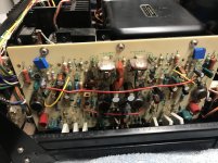
I was given a Sony TA-3200F that cosmetically is in very nice condition, but electrically it was pretty bad. When I received it both of the fuses on the power supply board were blown and there was a dead short in the amp. So I set to rebuilding it. I did a full electrolytic recap, including the main filters. The power supply board is basically new. New 1N5404s for the bridge rectifier, new 1% metal film resistors in place of the old carbon comps, new fuses, every other diode is new and of course the electrolytics. Pretty much same treatment for the amplifier board, all new diodes, etc. I thoroughly cleaned all of the controls, removed the outputs to measure them and put them back into the heatsink with new insulators and thermal compound.
Now here is the issue I’ve been chasing that’s causing me to lose all of my hair lol. This is the right channel only, when the gain control is all the way down I get a pretty decent buzz out of the speaker and it causes the heatsink to get pretty warm. Once it’s warmed up a bit then it makes the buzz when it’s all the way down and all the way up. Like just the last 5% of either extreme. After about an hour of music play then the buzzing in the right channel is there no matter what position the gain control is in. If it was only there when it was all the way down and stayed that way I wouldn’t care too much.
Here is what I’ve done. I thought it might have been the gain potentiometer would I pulled them both and swapped them between the channels. Didn’t help, so not the pot. A suggestion of a possible transistor starting to go was mentioned. I got my can of freeze spray to see if I could isolate the issue. I sprayed Q205 and the buzzing went away completely, eureka! I changed out the transistor and the buzz was still there. I sprayed the brand new transistor and the buzz went away completely until the device warmed up again. Same thing with Q204, sprayed it and buzz when away so I replaced it, no help. I sprayed D202 and again the buzz went away, so I pulled both and swapped them between the channels and no luck. Those are the only three devices that when sprayed make the buzz go away. I sprayed every other device on the board with no change at all. I also swapped the outputs between the channels to see if the buzz would move to the left channel.
Pretty much every transistor in the right side has been replaced. When I got the amp it looked like several had been replaced, maybe looking for the issue. There is a power limiter switch on the front that lets you choose full, 1/2, or 1/4. The buzz is only present in the full position. When in 1/2 or 1/4 the buzz goes away. With continuity checking it seems I have good ground where there should be.
I’m desperate lol. Oh and my unit is one of the highest serial numbered ones, above 811,000.
Dan
Attachments

Last edited:
Have you set the bias and offset?
I have, sitting at 25mV bias and about .5-1.5mV offset.
Dan
Quick thoughts not fully thought through...
See if the problem remains if you 'break' the Q/R connection to switch S5-2 while also shorting R202 out. That grounds the power amp input directly.
The power limiter looks interesting and you say only one channel is affected and that the noise disappears at lower power settings. Are D316/7 OK? Check both, not just the obvious right channel one.
Quick thoughts not fully thought through...
See if the problem remains if you 'break' the Q/R connection to switch S5-2 while also shorting R202 out. That grounds the power amp input directly.
The power limiter looks interesting and you say only one channel is affected and that the noise disappears at lower power settings. Are D316/7 OK? Check both, not just the obvious right channel one.
Hi, thank you for helping out. What do you mean exactly by breaking the Q/R connection of S5-2? Do you mean to just desolder them from the switch all together? I’m sorry, I’m just not sure what I’m supposed to do there. And shorting R202 out, just clip a lead from one of the resistor legs to ground I’m assuming?
D316 and D317 are new, 1N4004s. I’ll remove them just to double check though.
Thank you so much!
Dan
Hopefully this shines some light on what is going on. I swapped the signal wires coming from switch to the input of the board. So on the back of the amplifier board i just swapped the inputs between channels. So now it’s the left gain control that makes it hum, the right gain control does nothing, but oddly enough the buzz still comes from the right speaker output. So on a guess I started freezing components on the board in the left channel. Sure enough the same components in the left channel stop the buzzing. Q104, Q204, Q105, Q205, D102, and D202 eliminate the buzzing. It’s odd how freezing components in the left channel effects the right channel.
Dan
Dan
Have you tried poking around with an insulated tool (no freezing)?
I have, I keep a few chop sticks from take out around for that lol.
Dan
I have, I keep a few chop sticks from take out around for that lol.
Seems like a ground loop problem. Is the noise still present with no inputs connected, or with both inputs shorted?
Hopefully this shines some light on what is going on. I swapped the signal wires coming from switch to the input of the board. So on the back of the amplifier board i just swapped the inputs between channels. So now it’s the left gain control that makes it hum, the right gain control does nothing, but oddly enough the buzz still comes from the right speaker output...............
Lets stop there...
That's what you would expect to happen if the problem wasn't related to the pots and sockets and so on. You've swapped inputs and the fault is unchanged apart from now its the left pot doing all the action. The right channel output still buzzes.
............So on a guess I started freezing components on the board in the left channel. Sure enough the same components in the left channel stop the buzzing. Q104, Q204, Q105, Q205, D102, and D202 eliminate the buzzing. It’s odd how freezing components in the left channel effects the right channel.
Dan
This is the bit that doesn't compute...
At this point I would want to look with a scope at the content of this 'buzz' to be sure that it is just low frequency mains related noise and not some high frequency instability which can manifest as all sorts of weird noises (buzzing).
I think you mentioned that it looked like transistors had been swapped before. Older amps can be super critical on the devices used because old semiconductor manufacturing processes gave us slightly different characteristics to modern parts and often the amp design relies on this for stability. Swap in modern parts and things can go amiss. So a scope check is needed here.
The Q/R thing was really just to 100% isolate the amp input at board level and to shunt the input to ground be shorting the 680k.
Lets stop there...
That's what you would expect to happen if the problem wasn't related to the pots and sockets and so on. You've swapped inputs and the fault is unchanged apart from now its the left pot doing all the action. The right channel output still buzzes.
This is the bit that doesn't compute...
At this point I would want to look with a scope at the content of this 'buzz' to be sure that it is just low frequency mains related noise and not some high frequency instability which can manifest as all sorts of weird noises (buzzing).
I think you mentioned that it looked like transistors had been swapped before. Older amps can be super critical on the devices used because old semiconductor manufacturing processes gave us slightly different characteristics to modern parts and often the amp design relies on this for stability. Swap in modern parts and things can go amiss. So a scope check is needed here.
The Q/R thing was really just to 100% isolate the amp input at board level and to shunt the input to ground be shorting the 680k.
Excellent, those were my thoughts exactly. By swapping the input at the board and the issue not changing channels I pretty much eliminated all of the controls and inputs as the issue. I’ll get a pic of what the signal looks like on the scope in a few. Of the transistors changed I’ll also make a list of the originals and what was used as a replacement that way if anyone sees an obvious issue I can address it.
Thank you much,
Dan
Sorry, I woke up with chills and fever so I didn’t really do anything yesterday. So here is what the signal looks like on the scope. Let me know if you want me to take anymore pics with the scope set at certain settings.
Here were the transistor changes made.
Q201 2SA705 changed to ECG290A
Q202 2SC296A changed to ECG85
Q203 2SA705 changes to ECG290A
What I changed
Q204 2SA705 changed to KSA992
Q205 2SC1363 changed to ZTX696B
Q206 SPS885 changed to KSC3503
I was wrong, the rest of the transistors are stock.
Dan
Here were the transistor changes made.
Q201 2SA705 changed to ECG290A
Q202 2SC296A changed to ECG85
Q203 2SA705 changes to ECG290A
What I changed
Q204 2SA705 changed to KSA992
Q205 2SC1363 changed to ZTX696B
Q206 SPS885 changed to KSC3503
I was wrong, the rest of the transistors are stock.
Dan
Attachments
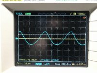
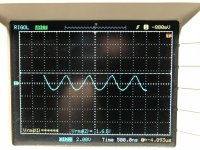
Interesting...
The time-base setting (is that 200ns per division?) implies that is a very high frequency signal.
F=1/T and so 200ns per div would be about 900ns for one cycle on the first image giving about 1.1MHz which is typical for instability.
Second image looks the same. You are showing 500ns per div which again is about 900ns when you just visually look at the screen.
Main related hum would be at either 50 or 60 Hz and the multiple of 100/120Hz for ripple. That would be 20 or 16.6 milliseconds and 10ms and 8.3ms.
So it does begin to look like there is some instability going on here and that could be really difficult to pin down as it is probably semiconductor related.
It may be possible to tame that but working 'live' on full mains means that you could just as easily provoke more oscillation that could be destructive. As always a bulb tester might be a good start, however you may find that limited supplies alter the problem and don't give a true indication of what works and what doesn't.
I would say nothing lost though in having a tweak.
Interesting...
The time-base setting (is that 200ns per division?) implies that is a very high frequency signal.
F=1/T and so 200ns per div would be about 900ns for one cycle on the first image giving about 1.1MHz which is typical for instability.
Second image looks the same. You are showing 500ns per div which again is about 900ns when you just visually look at the screen.
Main related hum would be at either 50 or 60 Hz and the multiple of 100/120Hz for ripple. That would be 20 or 16.6 milliseconds and 10ms and 8.3ms.
So it does begin to look like there is some instability going on here and that could be really difficult to pin down as it is probably semiconductor related.
It may be possible to tame that but working 'live' on full mains means that you could just as easily provoke more oscillation that could be destructive. As always a bulb tester might be a good start, however you may find that limited supplies alter the problem and don't give a true indication of what works and what doesn't.
I would say nothing lost though in having a tweak.
Excellent, thank you for the information. Do you have any thoughts on what the two channels would share that would cause right channel buzz to be eliminated when freezing left channel components?
Would a good start be shotgunning all of the small transistors?
Not sure where to start here.
Dan
The problem with instability is that 'pieces of wire' and 'lengths of PCB' don't appear as a low resistance due to the inherent self inductance of the runs. So when you alter things in one channel it can alter how the other channel 'sees' things.
(You can stick a pin through a piece of coax aerial cable seemingly shorting inner and outer and see no change in signal strength... at high frequency things behave differently to how they do at low frequency and DC)
I'm afraid I haven't any easy answers for this one... but if I had this in front of me then I would begin by looking at the data sheets for the original devices, particularly the output and drivers and the VAS (Q106). If Q101 and Q103 have been replaced then look at those as well.
The others shouldn't matter much as long as they are basically suitably specced with regard to voltage/current etc.
Using the scope you could try (but this is not without risk if it bursts into even worse instability) adding some capacitance across R119 which is the main feedback resistor. Perhaps try 47pF as a start.
There is also the compensation network of C106/107 at the VAS but that would really be one of the last things to tweak.
Unless the 'good' channel is using all original semiconductor you would have to alter both channels together, not just one at a time.
Its an interesting exercise but not an easy one.
I would definitely use the bulb at each stage and if the amp was OK with a bulb then retest on full mains.
Squarewave testing (say at 10Khz) can give a good idea of stability. The output should be clean with no ringing or other artifacts.
The problem with instability is that 'pieces of wire' and 'lengths of PCB' don't appear as a low resistance due to the inherent self inductance of the runs. So when you alter things in one channel it can alter how the other channel 'sees' things.
(You can stick a pin through a piece of coax aerial cable seemingly shorting inner and outer and see no change in signal strength... at high frequency things behave differently to how they do at low frequency and DC)
I'm afraid I haven't any easy answers for this one... but if I had this in front of me then I would begin by looking at the data sheets for the original devices, particularly the output and drivers and the VAS (Q106). If Q101 and Q103 have been replaced then look at those as well.
The others shouldn't matter much as long as they are basically suitably specced with regard to voltage/current etc.
Using the scope you could try (but this is not without risk if it bursts into even worse instability) adding some capacitance across R119 which is the main feedback resistor. Perhaps try 47pF as a start.
There is also the compensation network of C106/107 at the VAS but that would really be one of the last things to tweak.
Unless the 'good' channel is using all original semiconductor you would have to alter both channels together, not just one at a time.
Its an interesting exercise but not an easy one.
I would definitely use the bulb at each stage and if the amp was OK with a bulb then retest on full mains.
Squarewave testing (say at 10Khz) can give a good idea of stability. The output should be clean with no ringing or other artifacts.
Great, I’ll keep you informed of my progress. The left channel is completely stock as far as the transistors are concerned. In the end if I can’t revive it maybe I’ll see if I can source a bunch of NOS devices that are original to this amp.
Dan
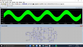
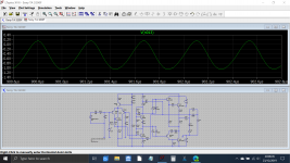
Just for fun I threw the design into LTspice... wow... in its raw form using the transistors I picked (all general purpose type) and without setting bias, in other words first run... and it oscillates just like yours does.
How 😎 is that 😉
The instability looks very similar and is around 2 and a bit Mhz.
One for another day...
How 😎 is that 😉
The instability looks very similar and is around 2 and a bit Mhz.
One for another day...
Attachments
Just for fun I threw the design into LTspice... wow... in its raw form using the transistors I picked (all general purpose type) and without setting bias, in other words first run... and it oscillates just like yours does.
How 😎 is that 😉
The instability looks very similar and is around 2 and a bit Mhz.
One for another day...
Really?! Does that mean I should really source original parts? That definitely would not be easy. Ugh.
Dan
Last edited:
I'd say near impossible to get known genuine parts on something this old...
Now I've just noticed a small error in my sim in that I missed C106 off completely, however the amp is still twitchy and is fairly close on the edge of stability even with this fitted and so I would suggest a little tweak of the compensation networks such as increasing C106/107 such as a 47pF for C107 and an 82 or 100pF for C106 and see if that improves things.
Also remember what I mentioned earlier about the bulb tester 🙂
SONY TA-3200F 4 units th
translated from japanese
translated from japanese
2SC926A this TR was the cause. It does not abnormal If you check the TR but will oscillate and put in circuit. I wonder if Hfe 363 as was abnormally high was still funny to have quite passed a number of years? . This kind of is the discovery is difficult. It was mounted to find the same TR from the junk box.
- Home
- Amplifiers
- Solid State
- Sony TA-3200F with hum/buzz in right channel when gain pot is all the way down